Vacuum alternating-current contactor for mechanical emergency

A technology of AC contactor and emergency action, which is applied to high-voltage air circuit breakers, high-voltage/high-current switches, electrical components, etc., can solve problems not mentioned, and achieve the effect of increasing synchronization

Inactive Publication Date: 2016-02-24
CHENZHOU DONGTANG ELECTRIC EQUIP
5 Cites 6 Cited by

AI-Extracted Technical Summary

Problems solved by technology

This provision is interpreted as: as long as the power supply is normal, it can be forced to start regar...

Abstract

The invention relates to a vacuum alternating-current contactor for mechanical emergency. The vacuum alternating-current contactor is composed of an insulated electrical isolation framework, a metal rear sealing plate, an electromagnetic operating mechanism, a manual operating mechanism and a vacuum switching tube; the electromagnetic operating mechanism is provided with a closing keeping buckle plate, a transmission crank arm, a closing armature, a closing coil and an opening spring; a counterbore is formed close to the edge in the longitudinal center of the closing armature, and the metal rear sealing plate is provided with a through hole opposite to the counterbore; a long pull rod penetrates through the through hole in the metal rear sealing plate, the capped portion of the long pull rod is connected with the counterbore of the closing armature, and the tapping portion of the long pull rod is connected with an L-shaped pull hook of a linkage rod of the manual operating mechanism. When a secondary control circuit fails or an electromagnetic coil of a vacuum switch is damaged, a fire-fighting water pump and a hydrant can be manually started for emergency by adopting the vacuum alternating-current contactor.

Application Domain

High-tension/heavy-dress switchesAir-break switches

Technology Topic

ContactorElectrical isolation +7

Image

  • Vacuum alternating-current contactor for mechanical emergency
  • Vacuum alternating-current contactor for mechanical emergency
  • Vacuum alternating-current contactor for mechanical emergency

Examples

  • Experimental program(1)

Example Embodiment

[0025] The present invention will be further described below in conjunction with the drawings and embodiments.
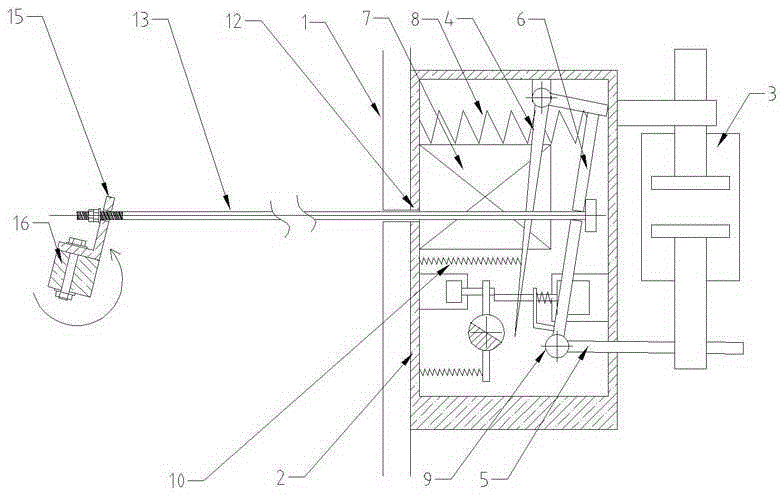
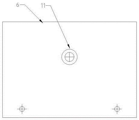
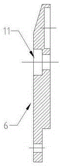
[0026] A vacuum AC contactor capable of mechanical emergency action, which is composed of an insulating power isolation frame 1, a metal back sealing plate 2, an electromagnetic operating mechanism, a manual operating mechanism and a vacuum switch tube component 3. The electromagnetic operating mechanism has a closing and holding The gusset 4, the driving arm 5, the closing armature 6, the closing coil 7, the opening coil and the opening spring 8. Among them, the inflection point of the driving arm 5 is installed on the closing shaft 9, and one of the driving arm 5 The arm is the closing armature 6, the end of the arm tightly presses the opening spring 8, and the other arm is connected to the moving contact of the vacuum switch tube component 3; there is a closing coil 7 under the closing armature 6; the closing retaining plate 4 has a buckle at one end The plate tension spring 10 pulls, and the other end has a clasp to block the closing armature 6; it is characterized in that; at the longitudinal center position of the closing armature 6 and the upper (or side) position in the horizontal direction, a counterbore 11 is opened; The countersunk hole 11 passes through the hole from the inside to the outside. The diameter of the through hole is φ7.5mm. The hole has a countersunk depth of 4mm from the inside out; the diameter is φ12mm; There is also a through hole 12 at the upper position in the transverse direction; the through hole diameter is φ12mm; a long tie rod 13 passes through the through hole 12 on the metal rear sealing plate 2; the long tie rod 13 has a diameter of φ5mm and a length of 180mm; long tie rod The capped part 14 of 13 is connected to the countersunk hole 11 on the closing armature 6. The capped part of the long tie rod 13 has a thickness of 3.5mm and a diameter of φ11mm; the other end of the tap is 45mm long; the tapped part of the long tie rod 13 is connected to the manual The "L"-shaped pull hook 15 on the linkage rod 16 of the operating mechanism is connected.
[0027] The above-mentioned "L"-shaped pull hook 15 is fixed on the linkage rod 16 with a through hole φ7mm on one wing; the wing end of the other wing has a circular hole 17 with a circular hole φ10mm; let the tapped part of the long pull rod 13 pass through the circular hole 17, And there are two adjusting nuts for locking; "L" shaped hook 15 adopts national standard 50# angle iron, with a cutting width of 48mm; "L" shaped hook 15 has 2 pieces.
[0028] The above-mentioned manual operating mechanism adopts a spring energy storage type quick closing/ quick opening structure.
[0029] The linkage rod 16 of the manual operating mechanism is square and the output stroke is adjustable; the linkage rod 16 is 230mm long and 16mm wide; in the linkage rod 16 corresponding to the installation via position of the AC vacuum contactor, the parallel via tapping diameter is φ8mm.
[0030] Assembly method: Pass the long pull rod 13 through the closing armature 6 of the vacuum contactor and the metal rear sealing plate 2; install and fix the vacuum contactor and the manual operating mechanism; the longitudinal installation position of the long pull rod 13 is longer than the linkage rod of the manual operating mechanism The position of 16 is 31mm lower, and the lateral position is 8mm lower than the position of the linkage rod 16 of the manual operating mechanism; the "L"-shaped pull hook 15 is oriented and installed on the linkage rod 16, and the "L" shape is tightened with a double nut The extra tapping part outside the hook 15.
[0031] Functional description of the mechanism components: It has manual closing/opening function. There are two methods for motorized opening: one electric divide, that is, the opening can be realized by applying AC220V voltage to the opening coil; the other hand divide, that is, the manual operating mechanism is pulled The control handle can be opened to the opening position.
[0032] After actual measurement and testing, the stroke and pulling force of the manual operating mechanism completely meet the pull-in and release strokes of the closing armature 6 of the vacuum AC contactor that can be mechanically emergency action. And test that the vacuum switch tube component 3 can be reliably closed and disconnected. Because the linkage structure of the manual operating mechanism is simple and reliable, and after the adjusting nut is fixed, two sets of AC vacuum contactors can be driven at the same time to achieve synchronous suction and release.

PUM

no PUM

Description & Claims & Application Information

We can also present the details of the Description, Claims and Application information to help users get a comprehensive understanding of the technical details of the patent, such as background art, summary of invention, brief description of drawings, description of embodiments, and other original content. On the other hand, users can also determine the specific scope of protection of the technology through the list of claims; as well as understand the changes in the life cycle of the technology with the presentation of the patent timeline. Login to view more.

Similar technology patents

High-synchronicity spinning equipment

InactiveCN108728989AImprove synchronicitySmooth production process
Owner:徐州美亚纺织有限公司

A synchronous unlocking and releasing mechanism and a distributed locking and separating device

ActiveCN114013690BImprove synchronicityImprove structural rigidity
Owner:北京微纳星空科技有限公司

Fryer capable of turning over automatically

PendingCN114788647AImprove synchronicityImprove operational convenience
Owner:贵州轻工职业技术学院

Multi-aircraft formation control method and device based on pilot following

PendingCN114740863AImprove synchronicityStrong formation retention
Owner:轮趣科技(东莞)有限公司

Hydraulic control system for stacking horizontal suction cup translation hydraulic motor device

PendingCN111140560AImprove synchronicity
Owner:中重科技(天津)股份有限公司

Classification and recommendation of technical efficacy words

  • Improve synchronicity

Method and device for generating high-precision synchronous clock

InactiveCN102611516Agood stabilityImprove synchronicity
Owner:CHENGDU FUHE POWER AUTOMATION COMPLETE EQUIP

Door and window physical property detection device

ActiveCN108489674Aavoid offsetImprove synchronicity
Owner:宁波和邦检测研究有限公司

Three-dimensional dynamic mechanical performing system with changeable contents

ActiveCN103212210AImprove synchronicity
Owner:BEIJING AEROSPACE TIMES OPTICAL ELECTRONICS TECH

Data receiver, data receiving system and data transmission system

ActiveCN104579570AImprove synchronicity
Owner:BRITE SEMICON SHANGHAI CORP

Measurement synchronization method, network equipment and terminal equipment

ActiveCN112312451AImprove synchronicityImprove reliability
Owner:DATANG MOBILE COMM EQUIP CO LTD
Why Eureka
Try Eureka