An End-Fire Directional Antenna

A technology of directional antennas and reflectors, which is applied in the direction of antenna, antenna grounding switch structure connection, radiation element structure, etc., can solve the problems of poor gain, narrow working frequency band, large lateral size of antenna, etc., to reduce volume and improve antenna Effects of gain and noise avoidance

Active Publication Date: 2016-06-01
JIANHU GUOCHUANG MACHINERY MFG CO LTD
View PDF4 Cites 0 Cited by
  • Summary
  • Abstract
  • Description
  • Claims
  • Application Information

AI Technical Summary

Problems solved by technology

The main problem that restricts the application of Yagi antennas in handheld devices is that the horizontal size of the antenna is too large, which is the main problem that needs to be solved
At the same time, after reducing the volume of the Yagi antenna, its working frequency band is narrow, and the problems of poor gain need to be solved urgently

Method used


Image

  • An End-Fire Directional Antenna

Examples


Embodiment Construction

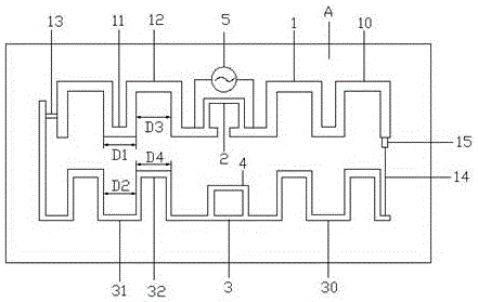
[0026] Please refer to figure 1 , the present invention is an end-fire directional antenna, which includes an exciter 1, and the exciter 1 includes two excitation arms 10, and the two excitation arms 10 are several gate-shaped folding lines. The gate fold line includes an actuator convex portion 11 and an actuator concave portion 12 . The two excitation arms 10 are symmetrical structures. Two ends of the two excitation arms 10 close to each other are respectively connected to the two ends of the tuner 2 . The two ends where the two exciting arms 10 are close to each other are the two ends where the feeding point is provided. The tuner 2 is a meander segment structure. At the same time, the tuner 2 may also have an arc segment structure.

[0027] A reflector 3 is arranged opposite to the exciter 1, and the reflector 3 is a bent vibrator structure, and the reflector 3 is composed of several gate-shaped folded lines. It is also a symmetrical structure. The reflector 3 inclu...


PUM


Abstract

The invention discloses an end-fire directional antenna, which comprises an exciter, a tuner, a reflector, an excitation source and a phase modulator, wherein the exciter comprises two excitation arms; the excitation arms are a plurality of portal broken lines; each portal broken line comprises an exciter bulge and an exciter recess; two ends of the tuner are connected with the two excitation arms respectively; the reflector is arranged oppositely to the exciter and comprises two reflection arms; each reflection arm comprises the plurality of portal broken lines; each reflection arm is provided with a reflector recess which is arranged oppositely to each exciter bulge; the exciter bulges and the reflector recesses are the same in width; each reflection arm is also provided with a reflector bulge which is arranged oppositely to each exciter recess; the exciter recesses and the reflector bulges are the same in width; two ends of the excitation source are connected with the two excitation arms respectively; the excitation source is located at one side, far away from the reflector, of the exciter; and the phase modulator is connected to the middle part of the reflector. The end-fire directional antenna has the advantages that the size of the antenna can be reduced; the gain can be improved; the noise can be lowered; the directivity can be improved; and the frequency can be adjusted.

Description

technical field [0001] The invention relates to an end-fire directional antenna, in particular to a small antenna terminal used as an ultra-high frequency radio frequency identification handset. Background technique [0002] Along with the development trend of miniaturization and portability of electronic equipment, radio frequency identification equipment also needs to meet such requirements. At present, the radio frequency identification miniaturization equipment is a handheld device, which can be flexibly used to collect label information. For example, the stacked items only need to be scanned by the staff with a portable device to complete the information collection. Therefore, , RFID handsets have great application prospects. In the hardware of the handheld, both the control circuit part and the information processing part can be miniaturized by using integrated circuit technology or modules, and the antenna occupies the largest space, because the size of the antenna a...

Claims


Application Information

Patent Timeline
Patent Type & Authority Patents(China)
IPC IPC(8): H01Q1/38H01Q1/50H01Q3/44H01Q19/10
CPCH01Q1/38H01Q1/50H01Q3/44H01Q19/10
Inventor 夏映湖
Owner JIANHU GUOCHUANG MACHINERY MFG CO LTD
Why Eureka
Try Eureka