Rotor for a turbine

一种涡轮机、燃气涡轮机的技术,应用在机械设备、发动机元件、发动机功能等方向,能够解决接触的临时、瞬间的丧失等问题,达到防止振荡、稳定保持、组装简化的效果

Inactive Publication Date: 2016-02-24
SIEMENS AG
View PDF7 Cites 2 Cited by
  • Summary
  • Abstract
  • Description
  • Claims
  • Application Information

AI Technical Summary

Problems solved by technology

Despite these measures, the risk of temporary, momentary loss of contact remains

Method used


Image

  • Rotor for a turbine
  • Rotor for a turbine
  • Rotor for a turbine

Examples


Embodiment Construction

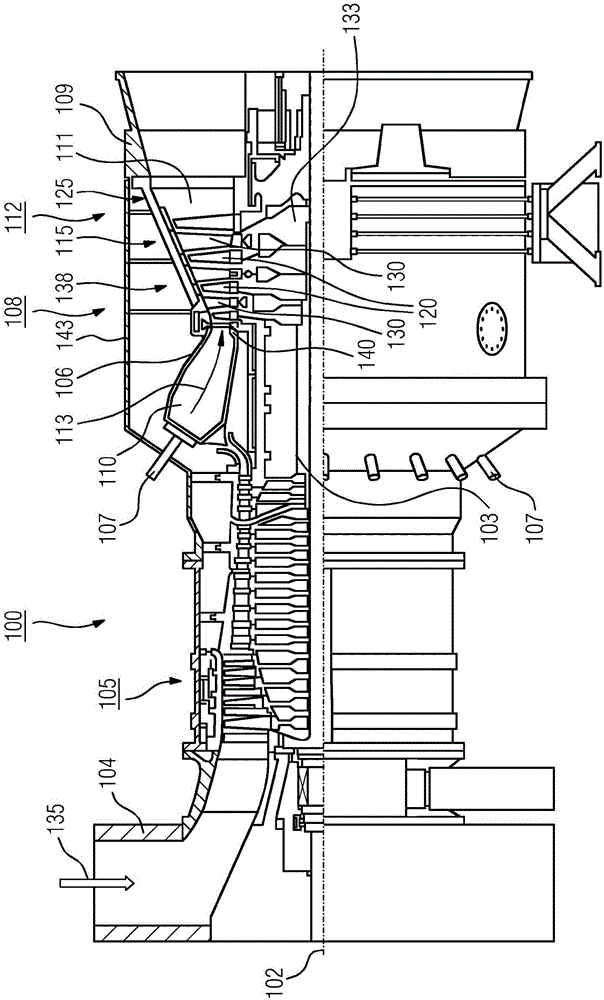
[0026] figure 1 The turbomachine 100 , here a gas turbine, is shown in partial longitudinal section. The gas turbine 100 comprises inside it a rotor 103 mounted to rotate about an axis of rotation (102) (axial direction) and also referred to as a turbine wheel. The following components follow one another along the rotor 103 : intake housing 104 , compressor 105 , constricted combustion chamber 110 with a plurality of coaxially arranged burners 107 , in particular annular combustion chamber 106 , turbine 108 and exhaust gas housing 109 . The annular combustion chamber 106 communicates with the annular hot gas pipeline 111 . There, for example, four series-connected turbine stages 112 form the turbine 108 . Each turbine stage 112 is formed by two rings of blades and airfoils. Viewed in the direction of flow of the working medium 113 , the row 125 formed by the rotor blades 120 follows the row of the stator guide vanes 115 in the hot gas duct 111 . The stator guide vanes 130...


PUM


Abstract

The invention relates to a rotor (103) for a turbine (100), comprising a plurality of rotor components (130) lined up in the axial direction and connected by means of a connecting rod (144), wherein a groove (152) which extends in the circumferential direction and is open in the axial direction is disposed on one of the rotor components (130), wherein a coupling element (154) running around the connecting rod (144) in order to support the connecting rod (144) is disposed in the groove (152). Said rotor is intended to enable particularly stable support of the connecting rod in order to prevent vibrations by technically simple means. For this purpose the coupling element (154) is disposed on a retaining element (150) connected to the connecting rod (144).

Description

technical field [0001] The invention relates to a rotor for a turbomachine comprising several rotor assemblies arranged in a row in the axial direction and connected by means of tie rods, wherein in one of the rotor assemblies is arranged a A directionally open slot in which a coupling element surrounding the tie rod is arranged to support the tie rod. Background technique [0002] A turbine is a fluid flow machine that converts the internal energy (enthalpy) of a flowing fluid (liquid or gas) into rotational energy and ultimately into mechanical drive energy. A proportion of the internal energy of the fluid flow is removed therefrom by the maximally vortex-free laminar flow around the turbine blades and transferred to the rotor blades of the turbine. This in turn sets the turbine shaft into rotation and useful power is output to a coupled work machine such as, for example, a generator. The rotor blades and shaft are the components of the moving turbine rotor or wheel that...

Claims


Application Information

Patent Timeline
Patent Type & Authority Applications(China)
IPC IPC(8): F01D5/02F01D5/06F01D5/10
CPCF01D5/066F01D5/025F01D5/026F01D5/10F05D2220/32F05D2230/60F05D2240/24F05D2240/60F05D2260/30
Inventor K·科斯塔马格纳S·东斯H·霍伊尔K·坎普卡K·科尔克U·劳戴吉P·施罗德V·威兹曼
Owner SIEMENS AG
Why Eureka
Try Eureka