Turbine blade

A technology of turbine blades and turbines, applied in the direction of blade support components, air transportation, engine functions, etc., can solve the problems of poor cooling air guidance, etc., and achieve the effects of increased service life, low stress load, and reduced decoupling

Inactive Publication Date: 2016-06-15
SIEMENS AG
View PDF5 Cites 0 Cited by
  • Summary
  • Abstract
  • Description
  • Claims
  • Application Information

AI Technical Summary

Problems solved by technology

However, this just shifts the problem to other areas or makes the cooling air in the blade less directable

Method used


Image

  • Turbine blade
  • Turbine blade
  • Turbine blade

Examples


Embodiment Construction

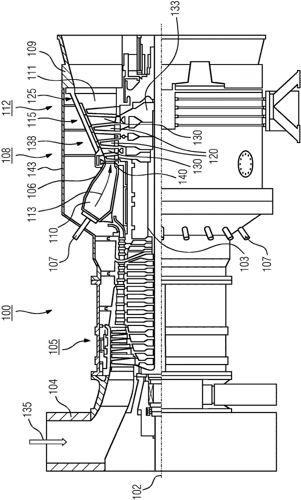
[0025] figure 1 The turbine 100 , here a gas turbine, is shown in longitudinal partial section. The turbine 100 is a fluid machine that converts the internal energy (enthalpy) of a flowing fluid (liquid or gas) into rotational energy and ultimately into mechanical drive energy.

[0026] The gas turbine 100 has internally a rotor 103 mounted such that it can rotate about an axis of rotation 102 (axial direction), which is also named turbine rotor. Along the rotor 103, the intake housing 104, the compressor 105, the torus-like combustion chamber 110, in particular the annular combustion chamber 106 with a plurality of coaxially arranged burners 107, the turbine 108 and the exhaust gas The housings 109 are arranged sequentially.

[0027] The annular combustion chamber 106 communicates with the annular hot gas passage 111 . There, for example, four turbine stages 112 connected one behind the other form the turbine 108 . Each turbine stage 112 is formed by two rings of blades. ...


PUM


Abstract

The invention relates to a turbine blade (120, 130) for a gas turbine (100), comprising a securing region (160) and a platform region (158) that adjoins the securing region and comprises a platform (162) on which a blade airfoil with a profiled cross-section and with a pressure-side wall (148) and a suction-side wall (150) is arranged, wherein each outer face of the pressure-side wall (148) and / or the suction-side wall (160) transitions into the platform surface via an outer rounded section (166). The turbine blade also comprises at least one cavity which is arranged in the blade airfoil and extends into the platform region (158) and in which at least one rib (154) is provided that connects the pressure-side wall (148) to the suction-side wall (150), said rib extending along a longitudinal direction of the blade airfoil so as to divide the cavity. The turbine blade is to have a greater service life using technically simplified means. This is achieved in that at least one slot (168) is introduced into the rib (154) in the platform region (158), said rib passing through the rib (154) and being arranged in the longitudinal direction.

Description

technical field [0001] The invention relates to a turbine blade for a gas turbine comprising: a fastening region and a platform region adjoining the fastening region and comprising a platform, a blade airfoil having a profiled cross-section and having a pressure sidewall and a suction sidewall is arranged on a platform, wherein the outer sides of the pressure side wall and / or the suction side wall each meet into the platform surface via an outer rounded section, and include at least one cavity arranged in the blade airfoil and extending to In the region of the platform and in which there is arranged at least one rib connecting the pressure side wall to the suction side wall, said rib extending in the longitudinal direction of the blade airfoil, subdividing the cavity. Background technique [0002] Turbine blades of the type mentioned above are used in gas turbines to convert the energy of a hot gas flow into rotational energy. They typically have a blade airfoil pierced by ...

Claims


Application Information

Patent Timeline
Patent Type & Authority Applications(China)
IPC IPC(8): F01D5/14F01D5/18
CPCF01D5/143F01D5/187F05D2260/941Y02T50/60F01D5/18F01D5/3007F01D9/02F01D25/12F05D2220/32F05D2240/81F05D2260/22141F05D2260/232
Inventor F·阿玛德C·门克R·拉杜洛维克
Owner SIEMENS AG
Why Eureka
Try Eureka