Turbine blade

A technology of turbine blades and turbines, which is applied to the supporting elements of blades, air transportation, engine functions, etc., and can solve problems such as limited operating temperature

Inactive Publication Date: 2016-03-23
SIEMENS AG
View PDF5 Cites 0 Cited by
  • Summary
  • Abstract
  • Description
  • Claims
  • Application Information

AI Technical Summary

Problems solved by technology

[0006] The thermal load on the turbine blades currently limits the efficiency of the turbine as these materials only allow a limited operating temperature

Method used


Image

  • Turbine blade
  • Turbine blade
  • Turbine blade

Examples


Embodiment Construction

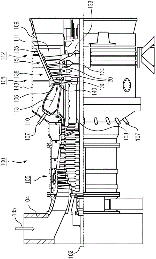
[0028] figure 1 A turbine 100 , here a gas turbine, is shown in longitudinal partial section. The gas turbine 100 has inside it a rotor 103 which is rotatably mounted about a rotation axis 102 (axial direction) and is also called a turbine rotor. Following each other along the rotor 103 are the intake casing 104, the compressor 105, the annular combustion chamber 110, the turbine 108 and the exhaust casing 109, wherein the annular combustion chamber, in particular the annular combustion chamber 106, has a plurality of coaxial Arranged burner 107.

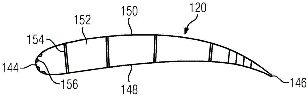
[0029] The annular combustion chamber 106 communicates with the annular hot gas pipeline 111 . Here, for example, four series-connected turbine stages 112 form the turbine 108 . Each turbine stage 112 is formed by two blade rings. As viewed in the flow direction of the working medium 113 , in the hot gas duct 111 , a row 115 of fixed blades is followed by a row 125 formed by movable blades 120 .

[0030] In this case, the stati...


PUM


Abstract

It is the intention for a turbine blade (120, 130), having a first cooling air duct (152) and a second cooling air duct (152) which is separated from the first cooling air duct (152) by a wall (154) and which has a main direction, wherein the first and the second cooling-air duct (152) are connected to one another by a first opening (160) in the wall (154), wherein the wall (154) has a second opening (164), to permit an improved cooling air action and thus higher operating temperatures and higher efficiency of the turbine. For this purpose, the second opening (164) is adjoined by a diverting duct (170), the main direction of which, in the region in which said diverting duct issues into the second cooling air duct (152), is oriented substantially parallel to the main direction of the second cooling air duct (152).

Description

technical field [0001] The invention relates to a turbine blade having a first cooling air duct and a second cooling air duct separated from the first cooling air duct by a wall, which is adjacent to the first cooling air duct and has a main direction, The first and second cooling air ducts are connected to each other at their respective ends by a first opening in the wall, wherein the wall has a second opening which divides the wall into a first part and a second part in the middle region. Background technique [0002] A turbine is an aerodynamic machine that converts the internal energy (enthalpy) of a flowing fluid (liquid or gas) into rotational energy and ultimately into mechanical drive energy. The laminar flow around the turbine blades, which is as free as possible from turbulence, has the effect of extracting from the fluid flow some of its internal energy, which is transferred to the moving blades of the turbine. These then set the rotation of the turbine shaft and...

Claims


Application Information

Patent Timeline
Patent Type & Authority Applications(China)
IPC IPC(8): F01D5/14F01D5/18
CPCF01D5/147F01D5/18F01D5/188Y02T50/60F01D5/02F01D5/187F01D9/041F01D25/12F05D2220/32F05D2240/12F05D2240/30F05D2260/202
Inventor F·阿玛德A·黑泽尔豪斯
Owner SIEMENS AG
Why Eureka
Try Eureka