Plug structure of bathroom container
A kind of pot plug, container technology
Active Publication Date: 2016-03-02
重庆博视知识产权服务有限公司
View PDF9 Cites 0 Cited by
- Summary
- Abstract
- Description
- Claims
- Application Information
AI Technical Summary
Problems solved by technology
However, the above-mentioned basin plug structure has the disadvantages of the following two aspects: 1. Since the basin plug is above the drainage pipe during drainage, the drainage efficiency of the sanitary products is reduced to a certain extent, and the drainage time is prolonged; At this time, the pollutants in the sewage will adhere to the container wall of the sanitary products. In this case, the water pipe is generally opened to rinse after the sewage is drained, and the basin plug needs to be opened, and then the container wall of the sanitary product is removed by tools. Simply scrub it again; however, the basin plug in the above-mentioned basin plug structure has been standing inside the container when it is waterproof, thus affecting the scrubbing of the container wall
Method used
View moreImage
Smart ImageViewing Examples
Examples
Embodiment 1
Embodiment 2
Login to View More PUM
 Abstract
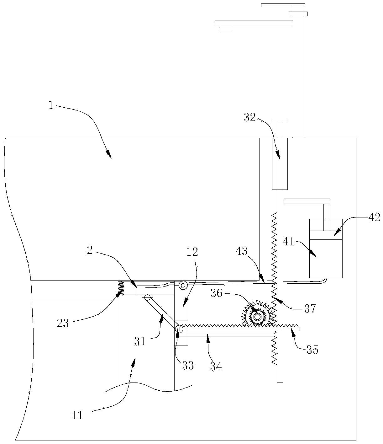
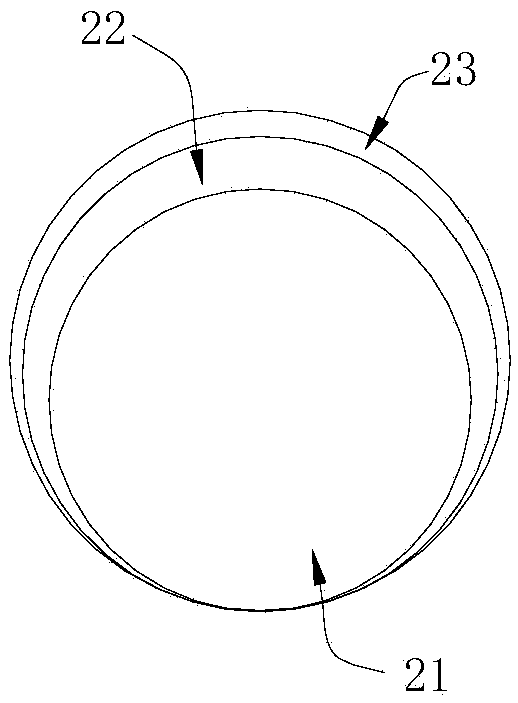
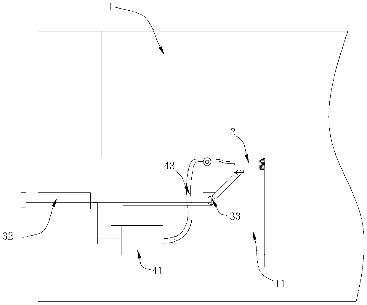
The invention relates to the field of bathroom accessories, in particular to a plug structure of a bathroom container. The plug structure is characterized in that a plug body is hinged to the upper port of the draining pipeline of the container, a drive device for driving the plug body to rotate is arranged on the container, and the plug body comprises a body part and an inflating part arranged on the outer side of the body part to allow the plug body to rotate smoothly; when the plug body rotates, an air pressure control device inflates and deflates the inflating part at the same time. By the arrangement, the plug structure has the advantages that manual taking and placing of the plug body are not needed; under a water storage state, the inflating part of the plug body expands and is arranged in the upper port of the draining pipeline in an interference fit manner to guarantee a sealing effect; under a water draining state, the plug body is accommodated in an accommodating groove, the flow of the draining pipeline is unaffected, the draining efficiency of the bathroom container is guaranteed, and cleaning of the bathroom container is unaffected due to the fact that the plug body is accommodated in a hidden manner.
Description
technical field [0001] The invention relates to the field of sanitary products, in particular to a basin plug structure of a sanitary container. Background technique [0002] The basin stoppers used in sanitary products such as basins, bathtubs or bathtubs have various structures. The basin body is formed into a water storage container by using the basin stoppers. After bathing, the basin stoppers are usually pulled out and then drained. In order to ensure a good drainage effect, the basin plug is installed at the bottom of the container; while the basin plug equipped with traditional bathroom products needs to be inserted or removed manually, especially when draining, the basin plug needs to be removed by hand through the sewage , when the sewage cleanliness is very low or in some public places, users are generally unwilling to manually remove the basin plug. Therefore, some existing bathroom products are equipped with a new type of basin plug structure. This type of basin...
Claims
Login to View More Application Information
Patent Timeline
 Patent Type & Authority Applications(China)
IPC IPC(8): A47K1/14E03C1/23
CPCA47K1/14E03C1/2302
Inventor 丁芸
Owner 重庆博视知识产权服务有限公司
Features
- R&D
- Intellectual Property
- Life Sciences
- Materials
- Tech Scout
- Unparalleled Data Quality
- Higher Quality Content
- 60% Fewer Hallucinations
Learn More Browse by: Latest US Patents, China's latest patents, Technical Efficacy Thesaurus, Application Domain, Technology Topic, Popular Technical Reports.
© 2025 PatSnap. All rights reserved.Legal|Privacy policy|Modern Slavery Act Transparency Statement|Sitemap|About US| Contact US: help@patsnap.com


