Vacuum cleaner structure

A technology for vacuum cleaners and dust cups, applied in vacuum cleaners, suction filters, cleaning equipment, etc., can solve problems such as deficiencies, and achieve the effects of comprehensive functions, maintaining high mute effect, and efficient cleaning ability.

Active Publication Date: 2016-03-02
NINGBO HAIJI ELECTRIC APPLIANCE
View PDF5 Cites 12 Cited by
  • Summary
  • Abstract
  • Description
  • Claims
  • Application Information

AI Technical Summary

Problems solved by technology

However, the current vacuum cleaners are still lacking in the setting of the air inlet and outlet, the separation ability and efficiency of dust and air, etc.

Method used


Image

  • Vacuum cleaner structure
  • Vacuum cleaner structure
  • Vacuum cleaner structure

Examples


Embodiment 1

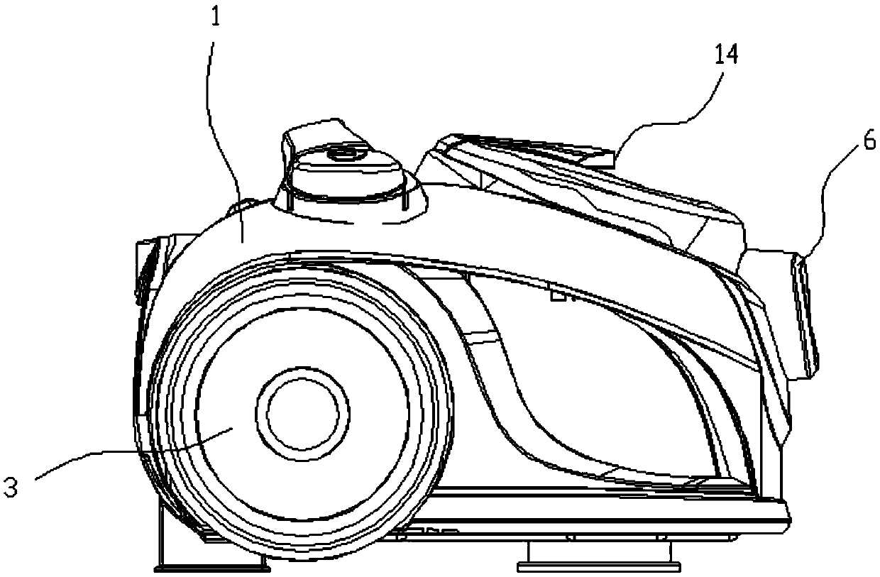
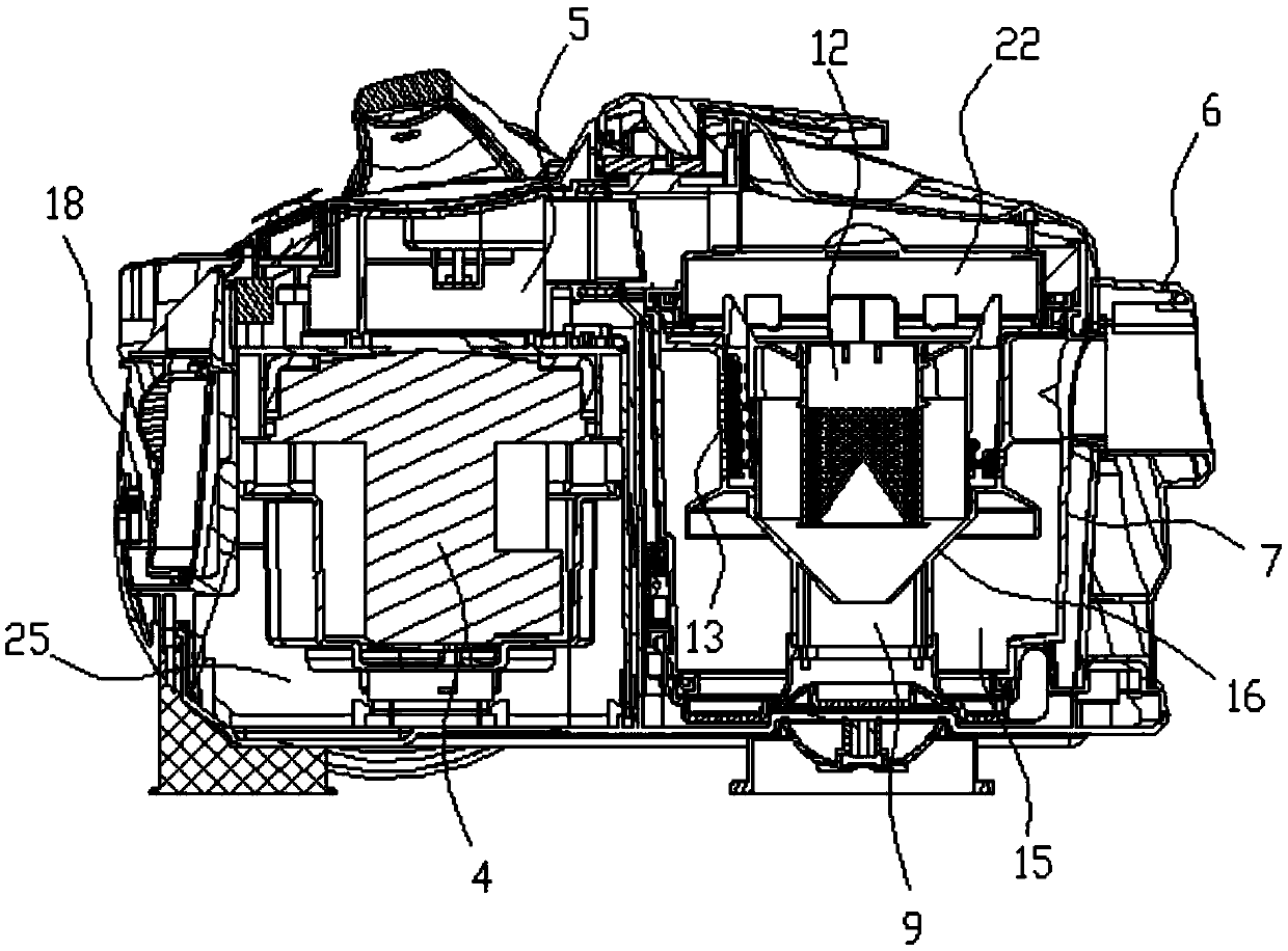
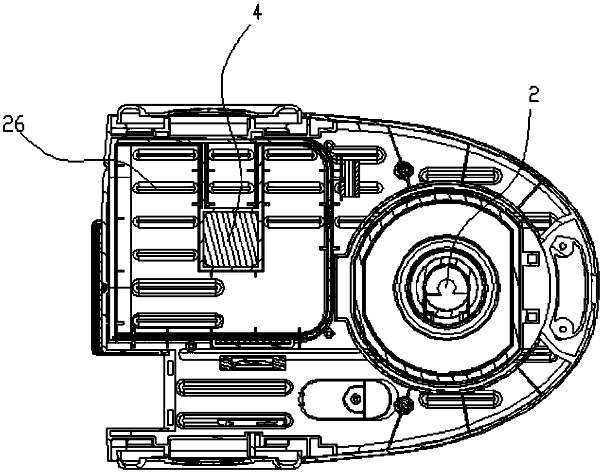
[0027] Embodiment 1: as Figure 1 to Figure 5 In the shown embodiment, a vacuum cleaner structure includes a main casing 1, a dust-absorbing mop, a universal wheel 2, and a plurality of moving wheels 3 arranged on the main casing. The main casing is provided with a suction motor 4 , the main casing is provided with a cup groove, and a dust cup assembly is arranged in the cup groove, and the dust cup assembly is clamped with the main casing, and a suction seat 6 is provided on the main casing, and the suction seat It is connected with the dust-absorbing mop through a suction pipe. The dust cup assembly includes a dust cup body 7, a cyclone cone 8, and an inner ash bin 9 below the cyclone cone. The cyclone cone is provided with sequentially connected The straight wind air inlet 10, the spiral downward air guide channel, and the cyclone air outlet, the straight wind air inlet is connected with the suction seat, and the cyclone cone is provided with a cone inner tube 11 coaxial wi...

Embodiment 2

[0034] Embodiment 2: the basic structure and implementation mode of this embodiment are the same as embodiment 1, and its difference is, as Figure 6 to Figure 9 As shown in , the dust-absorbing floor mop includes a ground mop base 29, an elbow pipe 30 for connecting with a dust suction pipe, and a number of rear ground wheels 31 and at least one front ground wheel 32 are arranged on the ground mop base. The bottom of the ground mop base is provided with a direct suction port 33, and the air intake direction of the direct suction port is upward, and the interior cavity of the ground mop is provided with a ground mop inner air duct 34, and the inner air channel of the ground mop communicates with the direct suction port. The elbow pipe is in communication with the inner air duct of the floor mop, and the base of the floor mop is provided with a brush bar 35 for cleaning the floor, and the brush bar is located directly in front of the suction inlet. The rear ground wheel and the...


PUM


Abstract

The invention discloses a vacuum cleaner structure which comprises a main machine shell, a dust suction mop, a universal wheel, a plurality of moving wheels and an induced draft motor. The main machine shell is provided with a dust cup component and a suction opening seat. The suction opening seat is connected with the dust suction mop through a dust suction pipe. The dust cup component comprises a dust cup, a cyclone cone and inner dust bin. The cyclone cone is provided with a straight wind inlet, a downwardly-spiral wind guide channel and a cyclone outlet which are sequentially communicated. The straight wind inlet is communicated with the suction opening seat. The cyclone cone is provided with a cone inner cylinder. The cone inner cylinder is provided with a vertical wind return channel communicated with the cyclone outlet. The cyclone outlet is communicated with the inlet of the vertical wind return channel and the inner dust bin. The outlet of the vertical wind return channel is communicated with the induced draft motor. The vacuum cleaner structure has the advantages that the wind inlet and outlet channels are reasonable in structure, and dust can be separated and collected by cyclone; the vacuum cleaner structure is high in dust suction ability and is provided with a multistage filter structure which is good in filter effect; noise during wind discharge can be reduced, and vibration and the noise can be reduced effectively to keep a good silent effect by a stability strengthening structure.

Description

technical field [0001] The invention belongs to the technical field of vacuum cleaners, and in particular relates to a structure of a vacuum cleaner. Background technique [0002] With the development of the times and the improvement of living standards, vacuum cleaners, especially household vacuum cleaners, have been widely used. A vacuum cleaner is an electrical appliance that uses a motor to generate negative air pressure in a sealed housing to suck in dust or garbage. The main function of the current vacuum cleaner is to recycle and clean up the dust and garbage on the floor, carpet, etc. in the home. However, the current vacuum cleaners are still lacking in the setting of the air inlet and outlet, the separation ability and efficiency of dust and air, and the like. Contents of the invention [0003] In order to overcome the deficiencies in the prior art, the present invention provides an inlet and outlet air duct with a reasonable structure, which can effectively co...

Claims


Application Information

Patent Timeline
Patent Type & Authority Applications(China)
IPC IPC(8): A47L9/16A47L9/10A47L9/00
CPCA47L9/00A47L9/10A47L9/127A47L9/1608
Inventor 周荣郑良宝
Owner NINGBO HAIJI ELECTRIC APPLIANCE
Why Eureka
Try Eureka