Dental model scanning device

A scanning device and dental mold technology, applied in dentistry, medical science, etc., can solve the problems of unsuitability for introduction and large size, and achieve the effect of improving the willingness to use, simple structure and reducing volume

Active Publication Date: 2016-03-02
METAL INDS RES & DEV CENT
View PDF12 Cites 4 Cited by
  • Summary
  • Abstract
  • Description
  • Claims
  • Application Information

AI Technical Summary

Problems solved by technology

At present, many products at home and abroad are large in size, and the appearance is mainly based on the strong image of industrial production line equipment, which is not suitable for introduction to clinics, hospitals or dental clinics

Method used


Image

  • Dental model scanning device
  • Dental model scanning device
  • Dental model scanning device

Examples


Embodiment Construction

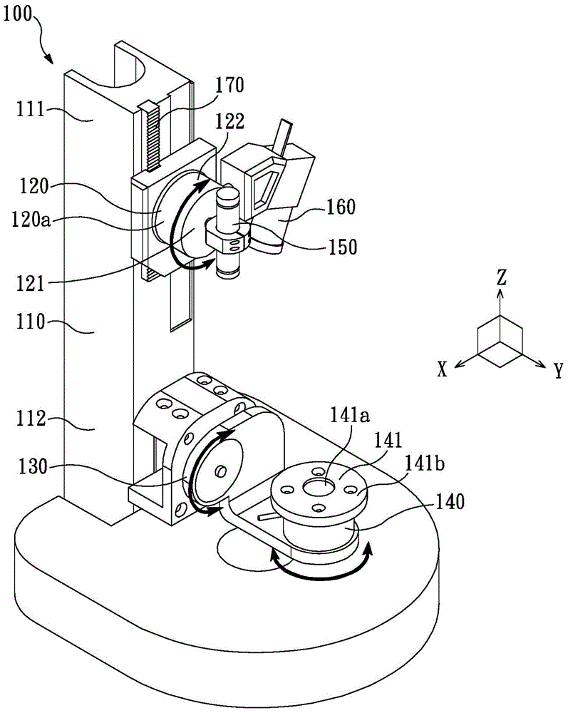
[0032] figure 2 It is a perspective view of the dental model scanning device according to the first embodiment of the present invention. The dental model scanning device 100 includes: a support column 110 , a first vertical rotation mechanism 120 , a second vertical rotation mechanism 130 , a horizontal rotation mechanism 140 , a light source module 150 and an image capturing module 160 . First, define a coordinate system in which the XYZ axes are perpendicular to each other. The first vertical rotation mechanism 120 is disposed at one end 111 of the support column 110 and uses the Y axis as a rotation axis for rotating relative to the support column 110 . The second vertical rotation mechanism 130 is disposed on the other end 112 of the support column 110 , and uses the Y-axis as a rotation axis to rotate relative to the support column 110 . The horizontal rotation mechanism 140 is disposed on the second vertical rotation mechanism 130 and uses the Z axis as a rotation axi...


PUM


Abstract

The invention discloses a dental model scanning device. A coordinate system with the X axis, the Y axis and the Z axis which are perpendicular to each other is defined. The dental model scanning device comprises a supporting column, a first vertically-rotating mechanism, a second vertically-rotating mechanism, a horizontal rotating mechanism, a light source module and an image taking module; wherein the first vertically-rotating mechanism is arranged at one end of the supporting column with the Y axis as the rotating axis; the second vertically-rotating mechanism is arranged at the other end of the supporting column with the Y axis as the rotating axis; the horizontal rotating mechanism is arranged on the second vertically-rotating mechanism and used for rotating with the Z axis as the rotating axis relative to the second vertically-rotating mechanism; the light source module is arranged in the axial direction of a shaft body of the first vertically-rotating mechanism and used for transmitting light towards the direction of the horizontal rotating mechanism, and the rotating direction of the light transmitted by the light source module is synchronized to the rotating direction of the first vertically-rotating mechanism; the image taking module is arranged in the radial direction of a shaft body of the first vertically-rotating mechanism.

Description

technical field [0001] The present invention relates to a dental model scanning device, in particular to a dental model scanning device utilizing multiple different rotating mechanisms. Background technique [0002] figure 1 It is a three-dimensional view of an existing dental model scanning device. When using the dental model scanning device 900, it is necessary to first place a tooth 950 to be scanned on the tooth holder 910, or place a single-jaw dental model (not shown) on the holder 920, and then drive the scanning The probe 930 moves and scans the teeth 950 to be scanned on the tooth jig 910 or the single-jaw dental model (not shown) on the jig 920 . Taking the scanning of the tooth 950 to be scanned as an example, after the swinging driver 911 drives the swing frame 912 to swing at a predetermined angle, the tooth 950 to be scanned can face the scanning probe 930 at different angles. Then, by driving the scanning probe 930 to move linearly along the slide rail 940 ...

Claims


Application Information

Patent Timeline
Patent Type & Authority Applications(China)
IPC IPC(8): A61C19/04
Inventor 蔡宗立胡博期陈彦廷林世桢杨义成
Owner METAL INDS RES & DEV CENT
Why Eureka
Try Eureka