Packing steel belt unwinding and cutting device

A shearing device and steel belt technology, which is applied to shearing devices, knives for shearing devices, shearing equipment, etc. problem, to achieve the effect of simple structure

Active Publication Date: 2016-03-02
ZHEJIANG HUASHUN METAL MATERIAL CO LTD
View PDF7 Cites 15 Cited by
  • Summary
  • Abstract
  • Description
  • Claims
  • Application Information

AI Technical Summary

Problems solved by technology

[0002] Packing steel belt refers to a kind of packing belt made of carbon steel, which is mainly used for binding goods. Now the commonly used packing steel belt is galvanized steel belt. The corrosion rate of zinc in the atmosphere is only that of steel in the atmosphere. 1 / 15 of the ratio, galvanized steel sheet is to protect the steel sheet with micro-dense galvanized layer from corrosion. High plasticity, toughness and mechanical strength, etc., the existing packing steel strip unwinding device has a complex structure and troublesome operation, it is difficult to unwind the packing steel strip quickly and efficiently, and it is easy to unwind the packing steel strip during the unwinding process. It causes the packing steel strip coil to loosen and slide down, which reduces the efficiency and quality of packing steel strip unwinding, and the existing packing steel strip unwinding device is difficult to move conveniently according to the needs of use, which increases the labor intensity of workers. Some packing steel strip unwinding devices require workers to hold the shearing device to cut the packing steel strip after unwinding the packing steel strip. It is difficult to cut the packing steel strip efficiently and accurately, which cannot meet the requirements of production. use needs

Method used


Image

  • Packing steel belt unwinding and cutting device
  • Packing steel belt unwinding and cutting device
  • Packing steel belt unwinding and cutting device

Examples


Embodiment Construction

[0014] In order to further describe the present invention, the specific implementation of a strapping steel strip unwinding and shearing device will be further described below in conjunction with the accompanying drawings. The following examples are explanations of the present invention and the present invention is not limited to the following examples.

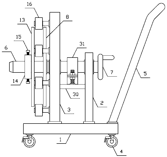
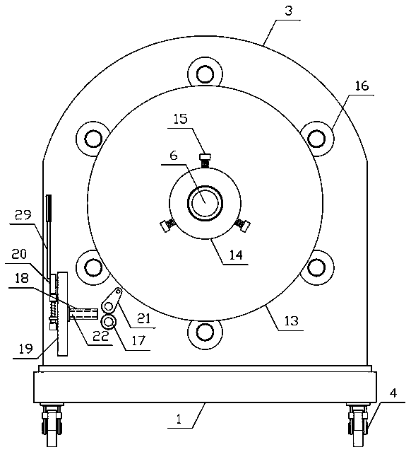
[0015] Such as figure 1 , figure 2 As shown, a packaged steel strip unwinding and shearing device of the present invention includes a translational base 1, a rotating bracket 2, an unwinding support 3 and a discharge shear mechanism, and a plurality of belt brakes are evenly arranged on the lower side of the translational base 1. Universal wheel 4, a translation handle 5 is provided obliquely on one side above the translation base 1, the unwinding support 3 and the rotating bracket 2 are respectively vertically arranged on both sides above the translation base 1, and the middle part of the unwinding support 3 rotates horizon...


PUM


Abstract

The invention discloses a packing steel belt unwinding and cutting device and belongs to the field of packaging machines and equipment. The packing steel belt unwinding and cutting device comprises a horizontal movement base, a rotary supporting frame, an unwinding support and a discharging and cutting mechanism. A rotary shaft is horizontally and rotatably connected to the middle of the unwinding support. A braking mechanism is arranged on the outer side of the portion, between the unwinding support and the rotary supporting frame, of the rotary shaft. A material supporting baffle is vertically and fixedly arranged on the portion, at one side of the unwinding support, of the rotary shaft. A limiting baffle is vertically arranged on the portion, at one side of the material supporting baffle, of the rotary shaft. A limiting sleeve is arranged at the outer end of the rotary shaft. The discharging and cutting mechanism comprises a rubber material guiding roller, a discharging plate, a cutting supporting frame and a cutting cam. The discharging plate is horizontally arranged at one side of the cutting supporting frame. An upper cutting knife and a lower cutting knife are arranged on the portions, at the upper side and the lower side of a discharge outlet, of the cutting supporting frame respectively. The packing steel belt unwinding and cutting device is simple in structure and convenient to use; a packing steel belt can be rapidly and efficiently unwound and cut stably and accurately, the working efficiency of workers is improved, and the use requirements are met.

Description

technical field [0001] The invention belongs to the field of packaging machinery and equipment, in particular to a packaging steel strip unwinding and shearing device. Background technique [0002] Packing steel belt refers to a kind of packing belt made of carbon steel, which is mainly used for binding goods. Now the commonly used packing steel belt is galvanized steel belt. The corrosion rate of zinc in the atmosphere is only that of steel in the atmosphere. 1 / 15 of the ratio, galvanized steel sheet is to protect the steel sheet with micro-dense galvanized layer from corrosion. High plasticity, toughness and mechanical strength, etc., the existing packing steel strip unwinding device has a complex structure and troublesome operation, it is difficult to unwind the packing steel strip quickly and efficiently, and it is easy to unwind the packing steel strip during the unwinding process. It causes the packing steel strip coil to loosen and slide down, which reduces the effic...

Claims


Application Information

Patent Timeline
Patent Type & Authority Applications(China)
IPC IPC(8): B23D15/04B21C47/18B23D35/00
Inventor 吴宁生
Owner ZHEJIANG HUASHUN METAL MATERIAL CO LTD
Why Eureka
Try Eureka