A support and clamping device for installing and welding the leakage channel of the high-pressure regulating valve of the steam turbine
A technology of high-pressure regulating valve and air leakage channel, which is applied in auxiliary devices, welding equipment, auxiliary welding equipment, etc., can solve problems such as poor positioning stability, achieve the effects of low cost, easy production and manufacturing, and overcome measurement errors
- Summary
- Abstract
- Description
- Claims
- Application Information
AI Technical Summary
Problems solved by technology
Method used
Image
Examples
specific Embodiment approach 1
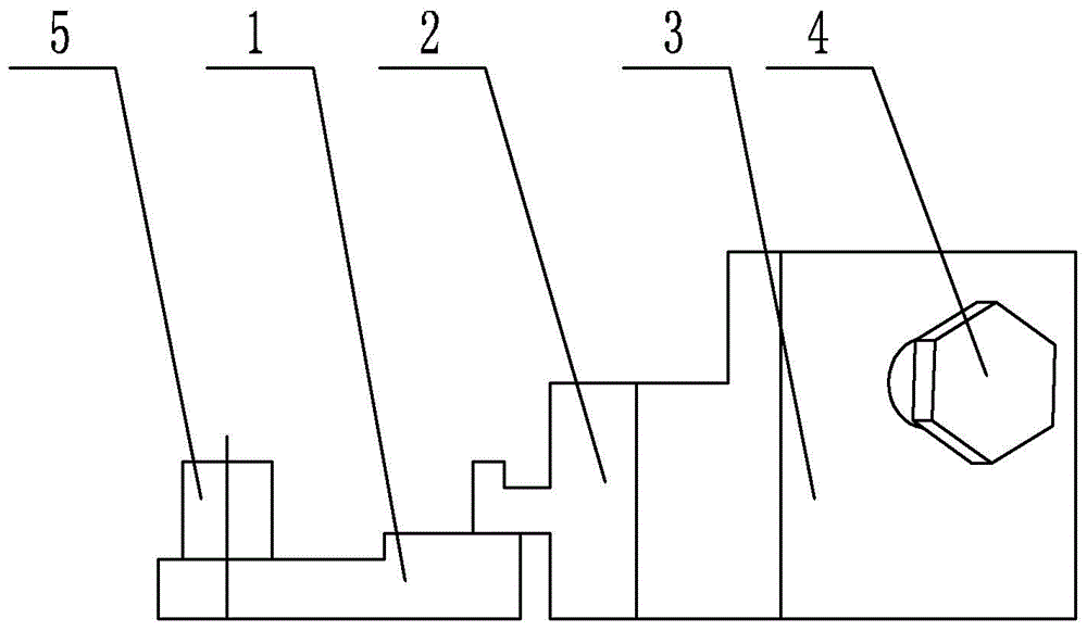
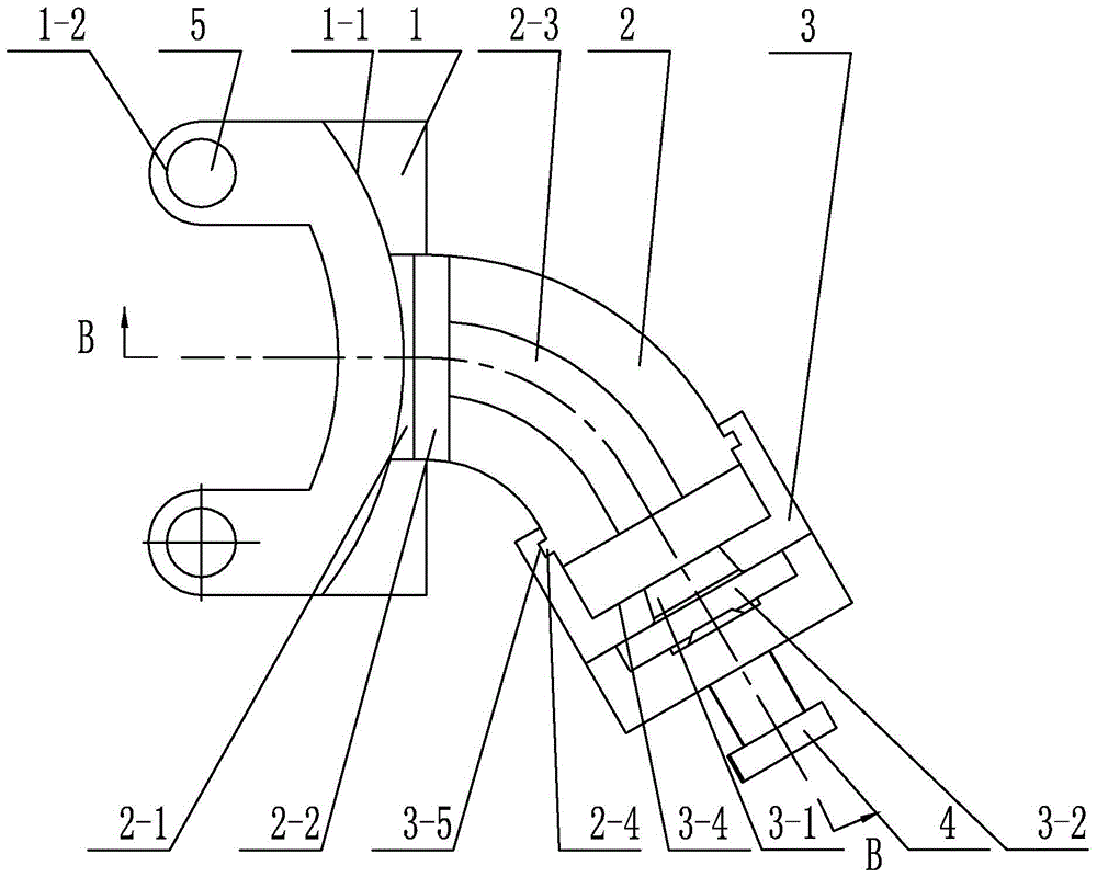
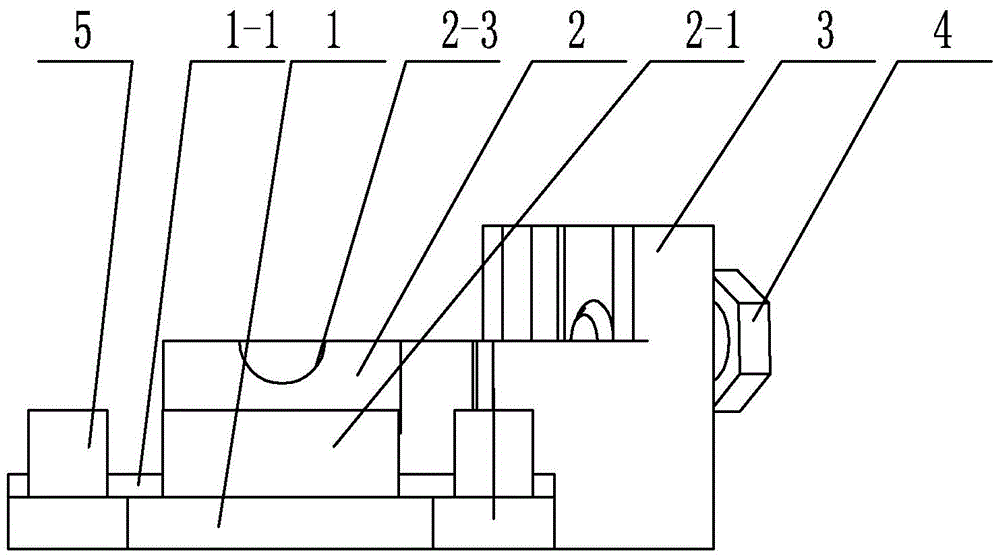
[0021] Specific implementation mode one: combine Figure 1 to Figure 11 Explain that a support and clamping device for welding the leakage channel of a steam turbine high-pressure regulating valve according to this embodiment includes a clamping seat 1, a connecting seat 2, a positioning block 3, a locking bolt 4 and two cylindrical pins 5, and the clamping seat 1 There is an arc groove 1-1 at the front end of the cylinder, the air regulating valve is set in the arc groove 1-1, a pin hole 1-2 is respectively arranged on both sides of the arc groove 1-1, and the lower end of the cylindrical pin 5 is inserted into the In the pin hole 1-2, the rear end of the clamp seat 1 is connected with the connecting seat 2, the shape of the connecting seat 2 is a quarter arc shape, and the upper and lower end surfaces of the connecting seat 2 are respectively provided with half The circular groove 2-3, the rear end of the connection seat 2 is connected with a positioning block 3, and the upp...
specific Embodiment approach 2
[0023] Specific implementation mode two: combination Figure 1 to Figure 8 Note that the front end of the connecting seat 2 in this embodiment is provided with a limit block 2-1, and the upper and lower ends of the limit block 2-1 are respectively provided with a limit groove 2-2, and the middle part of the rear end of the clip seat 1 is set at the limit In the groove 2-2, the groove wall of the limit groove 2-2 cooperates with the groove bottom of the arc groove 1-1. Other compositions and connection methods are the same as those in Embodiment 1.
[0024] Such a design can effectively position and connect the two when connecting the connecting base 2 and the clamping base 1. At the same time, the installation and disassembly of the connecting base 2 and the clamping base 1 can be completed without using other tools, which facilitates the conversion of the direction of the connecting base 2. , so as to realize two kinds of clamping in different directions of the left valve an...
specific Embodiment approach 3
[0025] Specific implementation mode three: combination Figure 1 to Figure 8 Note that the front end surface of the limiting groove 2-2 in this embodiment is an arc surface. Other compositions and connection methods are the same as those in the second embodiment.
[0026] This design realizes the cooperation between the limit groove 2-2 and the side wall of the valve core flange, making the positioning more accurate.
PUM
 Abstract
Description
Claims
Application Information
 - R&D
- Intellectual Property
- Life Sciences
- Materials
- Tech Scout
- Unparalleled Data Quality
- Higher Quality Content
- 60% Fewer Hallucinations
Browse by: Latest US Patents, China's latest patents, Technical Efficacy Thesaurus, Application Domain, Technology Topic, Popular Technical Reports.
© 2025 PatSnap. All rights reserved.Legal|Privacy policy|Modern Slavery Act Transparency Statement|Sitemap|About US| Contact US: help@patsnap.com


