Vehicle-mounted lifting return device of railway vehicle

A railway vehicle and vehicle technology, which is applied to railway car body components, equipment fixed on the vehicle, transportation and packaging, etc., can solve the problems of easy operation errors, slip hazards, hidden safety hazards and other problems of rescue and recovery personnel, and save precious time, reduce labor intensity, and ensure safety

Active Publication Date: 2016-03-02
CRCC HIGH TECH EQUIP CORP LTD +1
View PDF8 Cites 2 Cited by
  • Summary
  • Abstract
  • Description
  • Claims
  • Application Information

AI Technical Summary

Problems solved by technology

Rescue and recovery personnel are less safe when operating under the vehicle, and the whole process takes a long time
However, the patent document with the publication number CN104773187A does not take into account that the vehicle is tilted after derailment. During the recovery process, the vehicle cannot be adjusted to a horizontal state first. There is a danger of slipping during the recovery process, and relevant operations on the vehicle are required, resulting in rescue. The recovery personnel cannot monitor the entire recovery process within their own line of sight, and there are blind spots. Coupled with the noisy environment on site, the rescue recovery personnel are prone to operating errors and cannot be aware of it. This will bring major safety hazards to the recovery. And the distance between the rescue and recovery personnel and the vehicle is too close to ensure the safety of the recovery and recovery personnel

Method used


Image

  • Vehicle-mounted lifting return device of railway vehicle
  • Vehicle-mounted lifting return device of railway vehicle
  • Vehicle-mounted lifting return device of railway vehicle

Examples


Embodiment 11

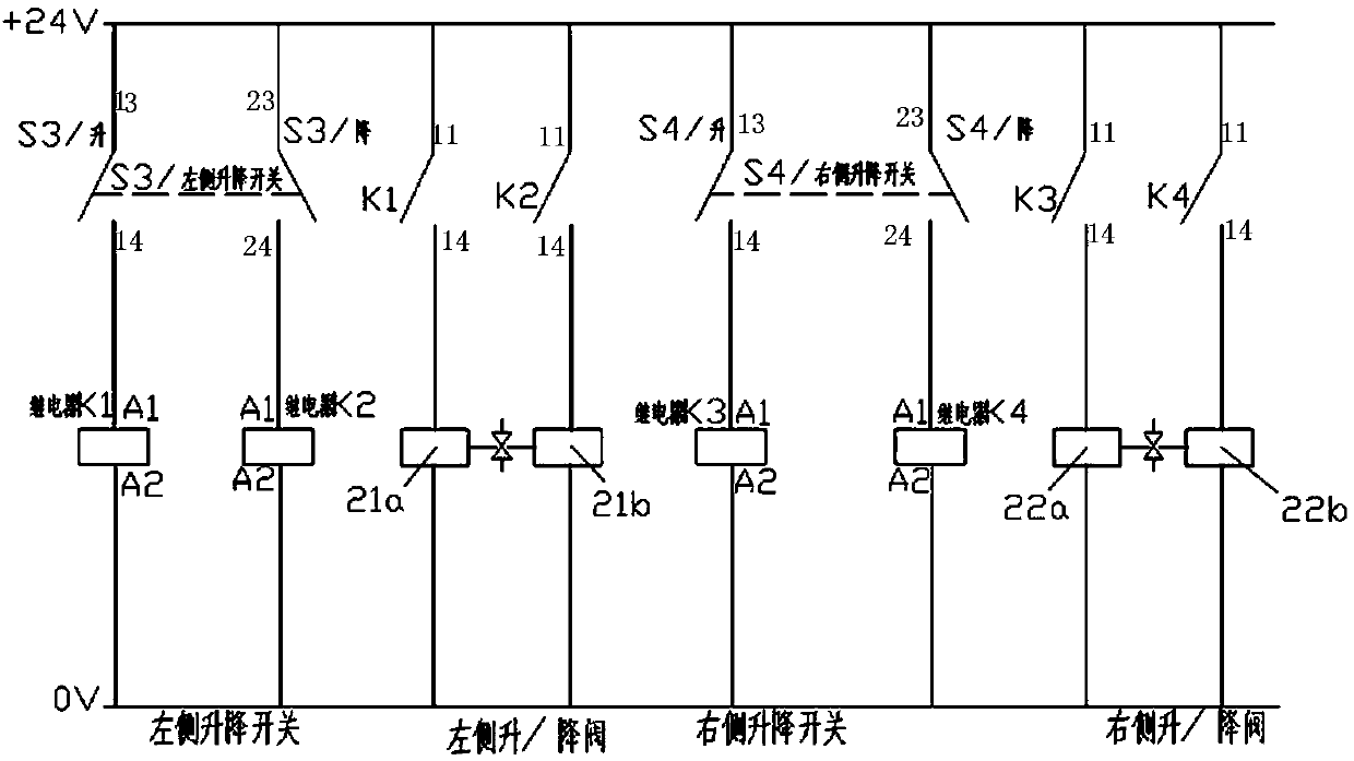
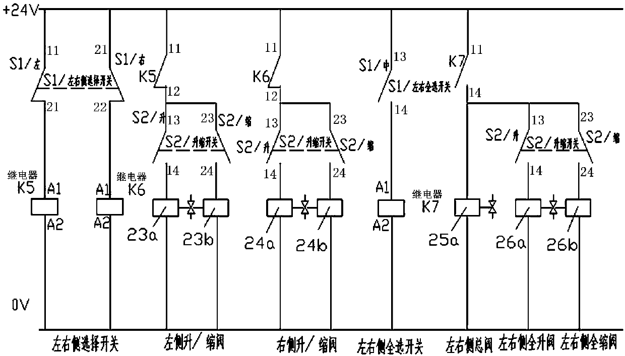
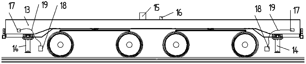
[0058] Example 1.1 : A kind of on-board hoisting device for railway vehicles, Figure 1-Figure 11 According to the first aspect of the present invention, it is a schematic structural diagram, an electrical schematic diagram and a hydraulic schematic diagram of a preferred embodiment of a vehicle-mounted recovery device for railway vehicles. The vehicle-mounted recovery device for railway vehicles provided in this embodiment includes: The lifting mechanism, the power source installed on the vehicle frame, the power supply, the docking socket and the control box placed on the vehicle, the control box is connected to the power supply, the relay and the docking socket through the cable 19, the switch or button on the control box can be used alone or Synchronously control the movement of the lateral power machine and the vertical power machine. The recovery mechanism includes a moving mechanism 4, which is connected to a guide rail 5, and the guide rail 5 is equipped with a latera...

Embodiment 12

[0067] Example 1.2 , the vehicle-mounted lifting device for railway vehicles is the same as that of Embodiment 1.1, except that the guide rail is a U-shaped guide groove.

Embodiment 13

[0068] Example 1.3 , the vehicle-mounted recovery device for railway vehicles is the same as that of Embodiment 1.1, except that the guide rail is a special-shaped guide groove.


PUM


Abstract

The invention discloses a vehicle-mounted lifting return device of a railway vehicle. The device comprises lifting return mechanisms mounted around a vehicle frame, a power source mounted on the frame, a power supply, a butt joint socket and a control box placed on a vehicle, wherein the control box is connected with the power supply, a relay and the butt joint socket through a cable (19); a switch or a button on the control box can singly or synchronously control actions of a transverse power machine and a vertical power machine; the lifting return mechanisms comprise moving mechanisms (4); the moving mechanisms (4) are connected with guide rails (5); and the transverse power machine (9) is mounted between the guide rails (5) through a mounting base I (8). The vehicle-mounted lifting return device of the railway vehicle is mounted on the railway vehicle frame without needing carrying, assembly and disassembly; and as rescue lifting return persons can take the control box to examine and determine the detained state around the frame to, the vehicle is guaranteed to locate in a horizontal state, and the operation is finished in the sight range of the rescue lifting return persons, the labor intensity is greatly reduced when the rescue lifting return safety is guaranteed.

Description

technical field [0001] The invention relates to a vehicle-mounted recovery device for a railway vehicle, in particular to a vehicle-mounted recovery device installed on a railway vehicle, and belongs to the technical field of railway rescue recovery equipment. Background technique [0002] A railway vehicle derailment accident is a serious accident that disrupts the order of railway transportation. After the accident, a safe and efficient recovery device is needed to carry out rescue and recovery work. There are various states of vehicle derailment, especially when the vehicle is tilted, which brings great difficulties and dangers to rescue and recovery, and it is easy to cause the vehicle to slip during recovery. The patent with the publication number CN204488819U discloses a hydraulic rerailer. This mechanism uses a lifting device placed above the rail, and the oil cylinder is lifted against the coupler, axle, frame, etc. The traversing car on the beam realizes the moveme...

Claims


Application Information

Patent Timeline
Patent Type & Authority Applications(China)
IPC IPC(8): B61K5/02
Inventor 叶永钦胡斌方健康徐建国任剡左后林蔡文涛
Owner CRCC HIGH TECH EQUIP CORP LTD
Why Eureka
Try Eureka