A wireless monitoring device for underground conditions

A wireless monitoring device and status technology, applied in the direction of measurement, wellbore/well components, earthwork drilling and production, etc., can solve the problems of unobtainable, only one set, unobtainable, etc. Environmentally friendly effect

Inactive Publication Date: 2018-03-30
CHINA UNIV OF PETROLEUM (EAST CHINA)
View PDF4 Cites 1 Cited by
  • Summary
  • Abstract
  • Description
  • Claims
  • Application Information

AI Technical Summary

Problems solved by technology

In the prior art, there are mainly two types of downhole monitoring, wired and wireless. The wired way is to establish an optical cable or cable connection between the ground or the location of the construction personnel and the downhole pipe string to obtain the downhole working condition parameters; the wireless way includes There are three kinds of mud pulse, electromagnetic wave and acoustic wave. The instruments and equipment manufactured based on these three methods can realize the monitoring of downhole conditions. Information parameters at the installation positions of instruments and equipment. This single-point measurement cannot obtain the overall conditions along the entire well, hole and pile, and cannot guarantee the accuracy of production. Second, there is no identification mechanism for the installation positions of multiple instruments and equipment in the well. and mechanism, multiple instruments and equipment cannot be installed at the same time, and the overall situation along the entire well, hole and pile cannot be obtained; the third is that the existing instruments and equipment can only simply perform the measurement and signal transmission tasks formulated before going down the well , unable to receive instructions from construction workers in real time, and complete specified tasks according to the instructions, and does not have interactive capabilities; the wireless method that does not require optical cables and cables is more suitable for underground operations in harsh working environments

Method used


Image

  • A wireless monitoring device for underground conditions
  • A wireless monitoring device for underground conditions

Examples


Embodiment

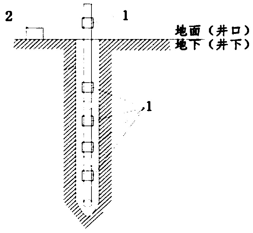
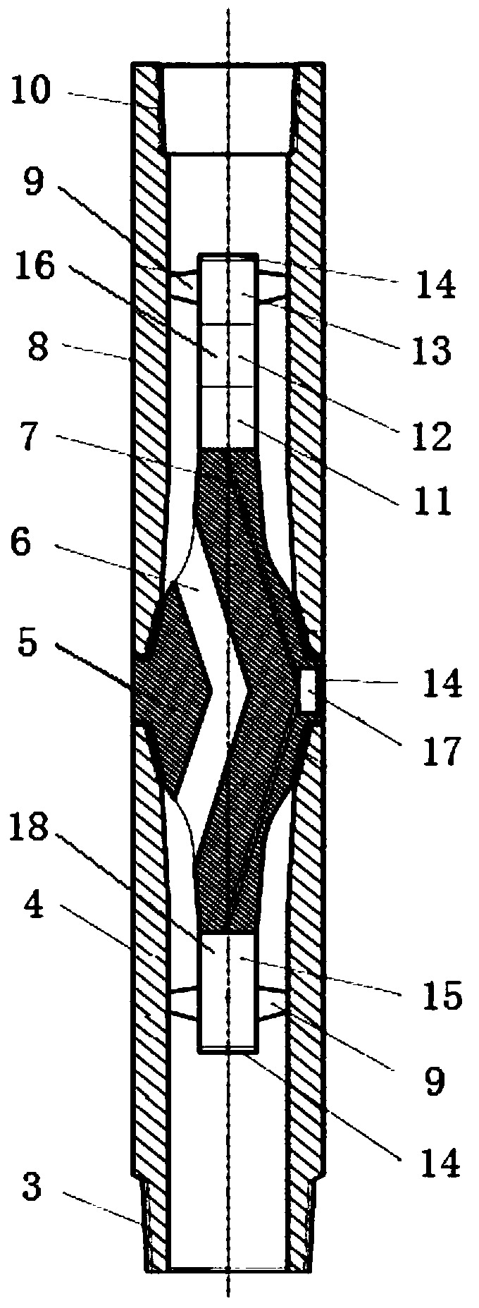
[0012] The main structure of the wireless monitoring device involved in this embodiment includes two functional parts of a monitoring unit 1 and a data processing terminal 2, the monitoring unit 1 and the data processing terminal 2 are connected through wireless communication; the monitoring unit 1 is composed of an external thread 3, a lower protective sleeve 4. Intermediate nipple 5, first through hole 6, second through hole 7, upper protective sleeve 8, centralizer 9, internal thread 10, sensor module 11, circuit module 12, battery module 13, cover 14, lower The instrument barrel 15, the upper instrument barrel 16, the groove 17, the transmitting transducer and the auxiliary circuit module 18 are combined; The end of the inner thread 10 is provided; the upper part of the intermediate short joint 5 is provided with an upper instrument barrel 16, and the inside of the upper instrument barrel 16 is provided with a battery module 13, a circuit module 12 and a sensor module 11 in...


PUM


Abstract

The invention belongs to the technical field of wireless monitoring, and relates to a wireless monitoring device for underground conditions. The main structure includes two functional parts: a monitoring unit and a data processing terminal. The monitoring unit and the data processing terminal are connected through wireless communication. Sleeve, intermediate nipple, first through hole, second through hole, upper protective sleeve, centralizer, internal thread, sensor module, circuit module, battery module, cover, lower instrument barrel, upper instrument barrel, groove It is composed of a transmitting transducer and an auxiliary circuit module, and is used for downhole condition monitoring in oil and gas drilling and production, downhole condition monitoring in coal mine drilling and production, pile hole monitoring in pile foundation construction in construction engineering, and other drills used Underground condition monitoring in long-distance pole or pipe string operation; its structure is simple, its principle is scientific and reasonable, its operability is strong, its use environment is friendly, its versatility is strong, and it is easy to popularize and use.

Description

Technical field: [0001] The invention belongs to the technical field of wireless monitoring, and relates to a wireless monitoring device for underground conditions, which is applied to the monitoring of underground conditions in oil and natural gas drilling and production, the monitoring of underground conditions in coal mine drilling and production, and pile holes in construction of pile foundations in construction projects Monitoring and other monitoring of subsurface conditions in long-distance operations using drill pipe or pipe strings. Background technique: [0002] In oil and gas drilling and production, coal mine drilling and production, construction engineering pile foundation construction and other long-distance underground operations using drill pipes or pipe strings, in order to ensure the accuracy of underground wells, holes and pile positions, real-time control of wells, holes, and piles is required. Various parameters of holes and piles, the azimuth, inclinati...

Claims


Application Information

Patent Timeline
Patent Type & Authority Patents(China)
IPC IPC(8): E21B47/00E21B47/12
CPCE21B47/00E21B47/12
Inventor 李志刚管志川梅中明
Owner CHINA UNIV OF PETROLEUM (EAST CHINA)
Why Eureka
Try Eureka