Stop valve centrifugal pump device

A technology of centrifugal pumps and stop valves, which is applied to components, pumps, and driving pumps of elastic fluid pumping devices, and can solve the problems of polluting the surrounding environment of machine pumps, wear, and large vibrations of centrifugal pumps, and achieves improved labor efficiency. Conditions, Simplified Piping System, Minor Effect of Wear

Inactive Publication Date: 2016-03-02
张学军
View PDF0 Cites 1 Cited by
  • Summary
  • Abstract
  • Description
  • Claims
  • Application Information

AI Technical Summary

Problems solved by technology

[0002] Before the centrifugal pumps on the market work, the pump body and the water inlet pipe must be filled with water to form a vacuum state. Since the self-priming pump must perform suction and exhaust work before each start of the pump, the water inlet pipe and the pump body The air can be completely exhausted before it can be started; according to the actual production and operation conditions on site, each time the centrifugal pump is operated, suction and exhaust operations must be performed, and the suction and exhaust process takes too long, and there is an early stage of exhaust, the centrifugal The vibration of the pump is relatively large, which will cause the overall vibration and wear of the centrifugal pump for a long time; the water filling in the pump of the centrifugal pump is insufficient, the dry grinding time of the mechanical seal is long, the wear is serious, the leakage exceeds the standard, and the surrounding environment of the pump is polluted; the service life of the mechanical seal is too short, and the centrifugal The maintenance frequency of pumps increases, and the cost of maintenance also increases, and many other problems

Method used


Image

  • Stop valve centrifugal pump device

Examples


Embodiment Construction

[0013] The present invention will be further described below in conjunction with specific examples.

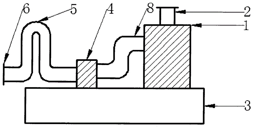
[0014] Such as figure 1 Shown: the shut-off valve centrifugal pump device is composed of an electric valve (4), a centrifugal pump (1), a support (3), an S-shaped pipeline (8) and a U-shaped pipeline (5).

[0015] The connection of the centrifugal pump (1) and the electric valve (4) is fixed by pipeline connection; the centrifugal pump (1) and the electric valve (4) are installed on the support (3); the centrifugal pump (1) and the electric valve (4) ) start and stop are synchronous.

[0016] The electric valve (4) is an electric ball valve.

[0017] The metal material of the bracket (3) is angle steel.

[0018] The electric valve (4) is installed in the middle of the S-shaped pipeline (8) and the U-shaped pipeline (5); the pipeline fixedly connected to one end of the electric valve (4) and the centrifugal pump (1) is the S-shaped pipeline (8); the electric valve The pipel...


PUM


Abstract

The invention discloses a stop valve centrifugal pump device which is composed of an electric valve, a centrifugal pump, a support and pipelines. The centrifugal pump and the electric valve are arranged on the support and are fixedly connected through the pipeline. The centrifugal pump and the electric valve are synchronously started and stopped. The pipeline through which one end of the electric valve is fixedly connected with the centrifugal pump is a linear pipeline or an S-shaped pipeline. The pipeline connected with the other end of the electric valve is a linear pipeline or a U-shaped pipeline. The stop valve centrifugal pump device has a complete self-suction function. The function of achieving permanent self-suction through drainage one time can be achieved only by ensuring that a certain amount of drainage water is stored in the pipelines before work. Therefore, a pipeline system is simplified, and labor conditions are improved; a centrifugal pump mechanical seal is free of dry grinding, slight in abrasion and small in leakage amount; and the stop valve centrifugal pump device has the beneficial effects of being compact in structure, convenient to operate, stable in running, easy to maintain, high in efficiency, long in service life and the like.

Description

technical field [0001] The invention relates to a pump body, in particular to a shut-off valve centrifugal pump device. Background technique [0002] Before the centrifugal pumps on the market work, the pump body and the water inlet pipe must be filled with water to form a vacuum state. Since the self-priming pump must perform suction and exhaust work before each start of the pump, the water inlet pipe and the pump body must be separated. The air can be completely exhausted before it can be started; according to the actual production and operation conditions on site, each time the centrifugal pump is operated, suction and exhaust operations must be performed, and the suction and exhaust process takes too long, and there is an initial exhaust, centrifugal The vibration of the pump is relatively large, which will cause the overall vibration and wear of the centrifugal pump for a long time; the water filling in the centrifugal pump is insufficient, the dry grinding time of the ...

Claims


Application Information

Patent Timeline
Patent Type & Authority Applications(China)
IPC IPC(8): F04D9/02F04D29/00F04D29/08
Inventor 张学军
Owner 张学军
Why Eureka
Try Eureka