
Reflux device for centrifugal compressor and centrifugal compressor having same

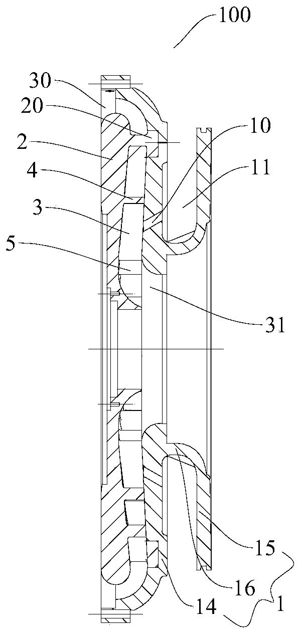
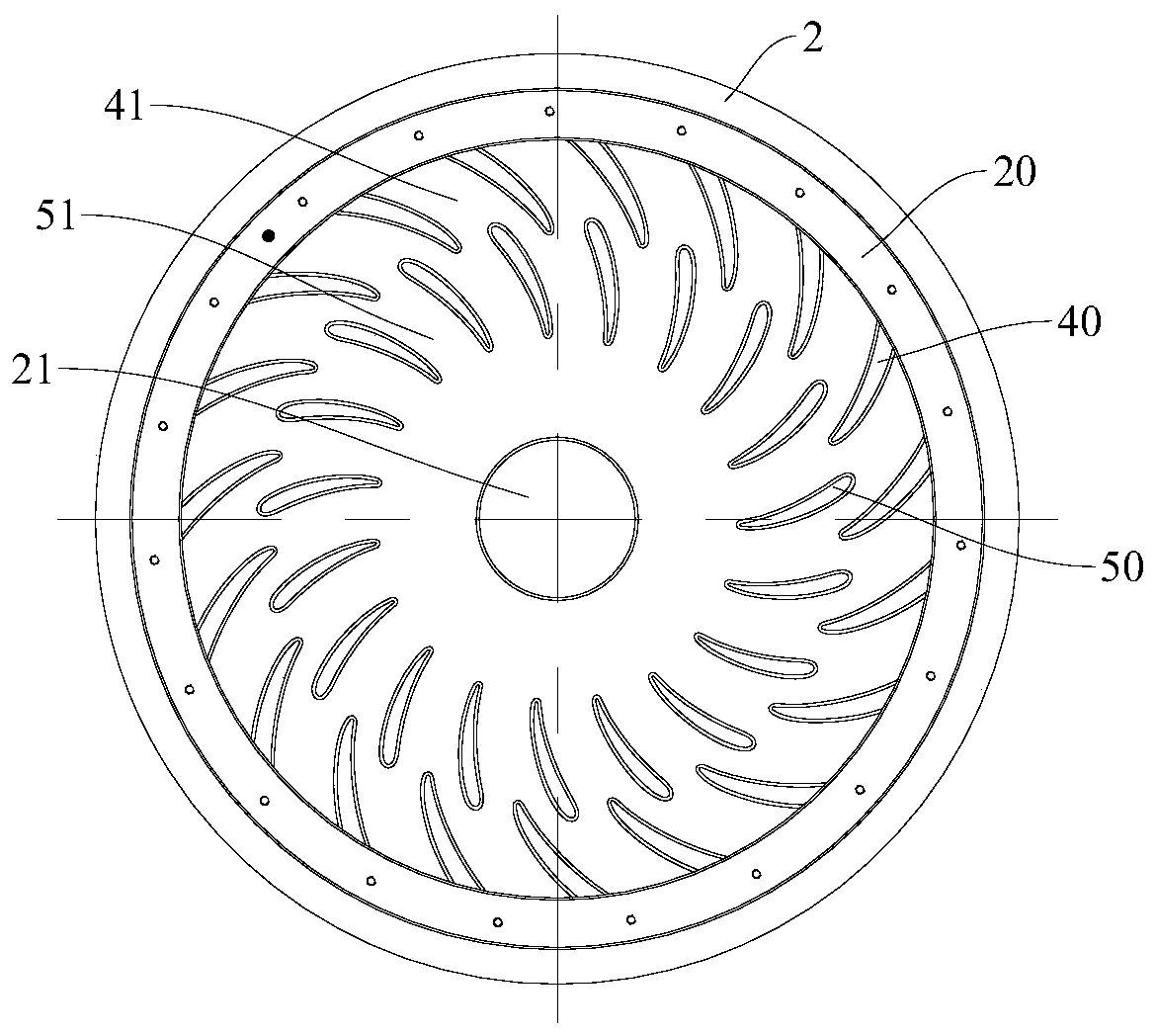
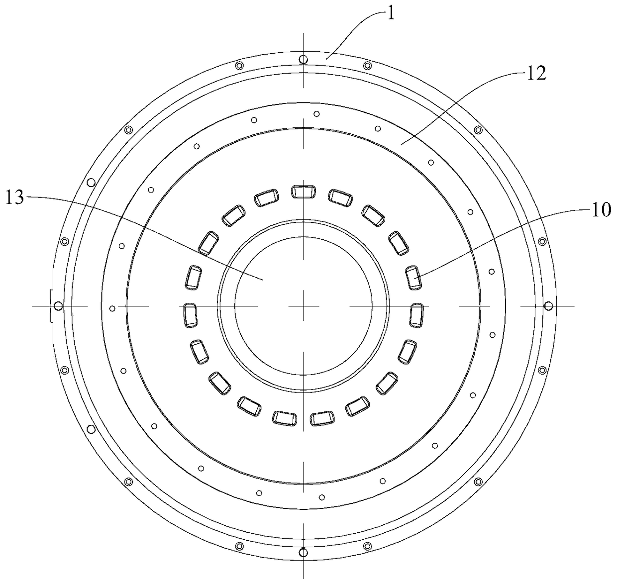
A technology of centrifugal compressor and reflux device, which is applied in the field of compressors, can solve the problems of increasing flow loss and outlet mixing loss, large wrap angle of single-leaf cascade derotation blades, and reduced blade derotation effect, so as to reduce gas Separation phenomenon, improve the effect of blade derotation, reduce the effect of gas separation

Active Publication Date: 2019-02-19
CHONGQING MIDEA GENERAL REFRIGERATING EQUIP
View PDF7 Cites 0 Cited by
  • Summary
  • Abstract
  • Description
  • Claims
  • Application Information

AI Technical Summary

Problems solved by technology

The reflux device in the existing multi-stage centrifugal refrigeration compressor generally adopts the structure of single-row cascade derotation blades and part of the gas supply area, but there are the following problems: 1. The gas is easy to separate at the trailing edge of the blades, which reduces the derotation effect of the blades, and the flow The loss is large, and the efficiency of the reflux device is low; 2. Part of the gas supply area will cause uneven flow field at the rear, increasing flow loss and outlet mixing loss; 3. Single-leaf cascade derotation blade has a large wrap angle, which is not easy to cast and processing

Method used


Image

  • Reflux device for centrifugal compressor and centrifugal compressor having same
  • Reflux device for centrifugal compressor and centrifugal compressor having same
  • Reflux device for centrifugal compressor and centrifugal compressor having same

Examples


Embodiment Construction

[0033] Embodiments of the present invention are described in detail below, examples of which are shown in the drawings, wherein the same or similar reference numerals designate the same or similar elements or elements having the same or similar functions throughout. The embodiments described below by referring to the figures are exemplary and are intended to explain the present invention and should not be construed as limiting the present invention.

[0034] In describing the present invention, it should be understood that the terms "center", "longitudinal", "transverse", "length", "width", "thickness", "upper", "lower", "front", " Back", "Left", "Right", "Vertical", "Horizontal", "Top", "Bottom", "Inner", "Outer", "Clockwise", "Counterclockwise", "Axial", The orientation or positional relationship indicated by "radial", "circumferential", etc. is based on the orientation or positional relationship shown in the drawings, and is only for the convenience of describing the presen...


PUM


Abstract

The invention provides a backflow device for a centrifugal compressor and a centrifugal compressor with the same. The backflow device comprises a wall surface component, a blade connector, first-row blades and second-row blades. The wall surface component comprises gas supply openings. The blade connector is fixed to the wall surface component. The first-row blades include a plurality of first blades and are arranged on the blade connector. The second-row blades include second blades and are arranged on the blade connector. In the radial direction of the blade connector, the second-row blades are located on the inner sides of the first-row blades and each first blade is spaced from the second blade. The backflow device has the advantages that the gas separation phenomenon is reduced, the blade de-swirling effect is improved, the flow loss is reduced and the efficiency is increased; the wrap angles of the first-row blades and the second-row blades re reduced, so that the casting difficulty is reduced.

Description

technical field [0001] The invention relates to the field of compressors, in particular to a reflux device for a centrifugal compressor and a centrifugal compressor with the same. Background technique [0002] The return channel element is also called the reflux device. In the multi-stage centrifugal refrigeration compressor, its function is to guide the swirling gas with strong tangential velocity flowing out of the previous stage diffuser to the impeller inlet of the next stage. In order to obtain the best For optimal design performance, the impeller inlet airflow must enter the impeller in a direction with a tangential velocity of zero or close to zero (only retaining the axial velocity). The reflux device in the existing multi-stage centrifugal refrigeration compressor generally adopts the structure of single-row cascade derotation blades and part of the gas supply area, but there are the following problems: 1. The gas is easy to separate at the trailing edge of the blad...

Claims


Application Information

Patent Timeline
Patent Type & Authority Patents(China)
IPC IPC(8): F04D29/44F04D17/12
Inventor 李镇杉吴昕辜永刚王永张海洲刘平平张恒海马丽君
Owner CHONGQING MIDEA GENERAL REFRIGERATING EQUIP
Learn More