Plate and tube type refrigerator efficient condenser
A condenser and plate-and-tube technology, which is applied in the field of high-efficiency condensers of plate-and-tube refrigerators, achieves the effects of high heat dissipation and cooling efficiency, reduced pressure drop difference, and reduced cost.
- Summary
- Abstract
- Description
- Claims
- Application Information
AI Technical Summary
Problems solved by technology
Method used
Image
Examples
Embodiment 1
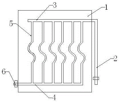
[0017] A high-efficiency condenser for a plate-and-tube refrigerator, comprising: an aluminum heat dissipation fixing plate 1, a microchannel pipe and a superheated steam inlet pipe 2; the microchannel pipe is fixed on the heat dissipation fixing plate 1 by riveting, and A distance of 1.5 cm is left between the lower surface of the channel tube and the upper surface of the heat dissipation fixed plate to ensure air circulation.
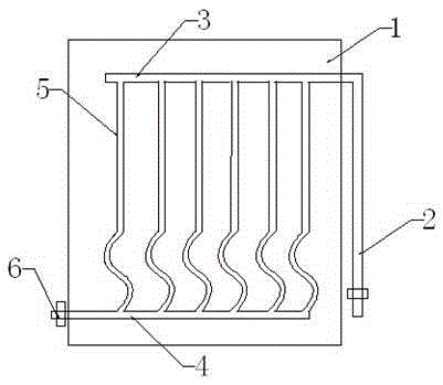
[0018] The micro-channel tube comprises an upper integrated tube 3, a lower integrated tube 4 and a vertical tube bundle 5, the superheated steam tube 2 communicates with the upper integrated tube, and the lower integrated tube 4 is provided with a condensate outlet 6; The vertical pipe bundle 5 is composed of a straight pipe section and an S-shaped pipe section; wherein, the straight pipe section has two ends, and the S-shaped pipe section is embedded between the two straight pipe sections.
[0019] In the high-efficiency condenser of the above-menti...
Embodiment 2
[0021] A high-efficiency condenser for a plate-and-tube refrigerator, comprising: a heat dissipation fixing plate 1, a microchannel pipe and a superheated steam inlet pipe 2; the microchannel pipe is fixed on the heat dissipation fixing plate 1 in the form of an adhesive, and A distance of 2 cm is left between the lower surface of the tube and the upper surface of the cooling plate to ensure air circulation.
[0022] The micro-channel tube comprises an upper integrated tube 3, a lower integrated tube 4 and a vertical tube bundle 5, the superheated steam tube 2 communicates with the upper integrated tube, and the lower integrated tube 4 is provided with a condensate outlet 6; The vertical pipe bundle 5 is composed of a straight pipe section and an S-shaped pipe section; wherein, each of the straight pipe section and the S-line pipe section has one section, and the straight pipe section communicates with the upper integrated pipe 3, and the S-shaped pipe section communicates with...
Embodiment 3
[0025] The difference from Example 2 is that the straight pipe section communicates with the lower manifold 4, and the S-shaped pipe section communicates with the upper manifold 3; the distance between the pipes is 15 cm.
[0026] Compared with existing condensers, the condenser in the above embodiment saves materials by more than 30%, and improves heat exchange efficiency by more than 10%.
PUM
| Property | Measurement | Unit |
|---|---|---|
| The inside diameter of | aaaaa | aaaaa |
| Straight line length | aaaaa | aaaaa |
Abstract
Description
Claims
Application Information
 - R&D
- Intellectual Property
- Life Sciences
- Materials
- Tech Scout
- Unparalleled Data Quality
- Higher Quality Content
- 60% Fewer Hallucinations
Browse by: Latest US Patents, China's latest patents, Technical Efficacy Thesaurus, Application Domain, Technology Topic, Popular Technical Reports.
© 2025 PatSnap. All rights reserved.Legal|Privacy policy|Modern Slavery Act Transparency Statement|Sitemap|About US| Contact US: help@patsnap.com


