Air conditioner for vehicles

a technology for air conditioners and vehicles, which is applied in the direction of refrigeration components, transportation and packaging, light and heating equipment, etc., can solve the problems of urgent need for improving the cooling performance, the limitation of increasing the efficiency of the entire system, and the limitation of improving the radiating performance and cooling efficiency (cop), so as to achieve optimal radiating performance and cooling efficiency, shorten the channel length of refrigerant, and reduce the amount of refrigerant pressure drop

Active Publication Date: 2015-03-17
HANON SYST
View PDF19 Cites 5 Cited by
  • Summary
  • Abstract
  • Description
  • Claims
  • Application Information

AI Technical Summary

Benefits of technology

[0039]According to this document, the refrigerant cycle of an air conditioner for vehicles has the first evaporating unit and the second evaporating unit disposed upstream and downstream in a direction in which the air blown from the single blower flows to control the amount of refrigerant supplied to each evaporating unit, thereby making it possible to obtain the optimal radiating performance (cooling performance) and cooling efficiency (COP) through the design of the optimal refrigerant flow ratio depending on the cooling load.
[0040]Further, according to this document, the refrigerant cycle of an air conditioner for vehicles shortens the channel length of the refrigerant and decreases the pressure drop amount of the refrigerant by using the evaporator including the first evaporating unit and the second evaporating unit to increase the refrigerant flow and improve the evaporation conditions, thereby making it possible to increase the efficiency of the entire system.
[0041]In addition, according to this document, the refrigerant cycle of an air conditioner for vehicles can simultaneously supply the refrigerant in two states to the first evaporation unit and the second evaporation unit of the evaporator, respectively, by using the expansion valve in which the first supply passage and the second supply passage are formed.

Problems solved by technology

However, since the above-mentioned refrigerant cycle has a limitation in increasing cooling performance, improvement for increasing the cooling performance is urgently required.
Further, there is a limitation in increasing the efficiency of the entire system due to the loads of the compressor 1.
However, since the air conditioner to which the above-mentioned refrigerant cycle is applied uses the evaporator including the single evaporator unit, it has a limitation in improving the radiating performance and the cooling efficiency (COP).

Method used


Image

  • Air conditioner for vehicles
  • Air conditioner for vehicles
  • Air conditioner for vehicles

Examples


Embodiment Construction

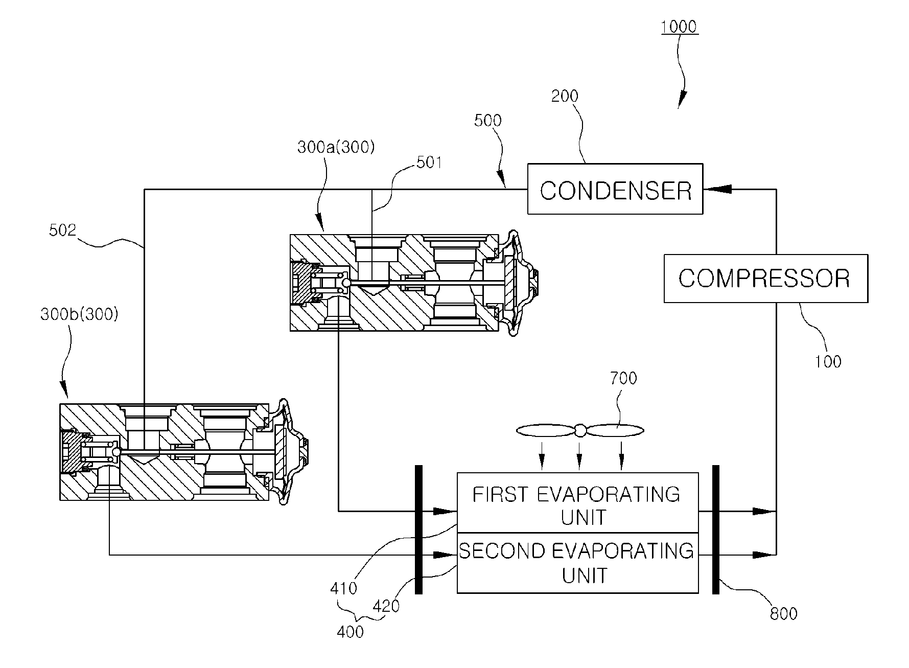
[0056]1000: REFRIGERANT CYCLE OF AIR CONDITIONER FOR VEHICLES

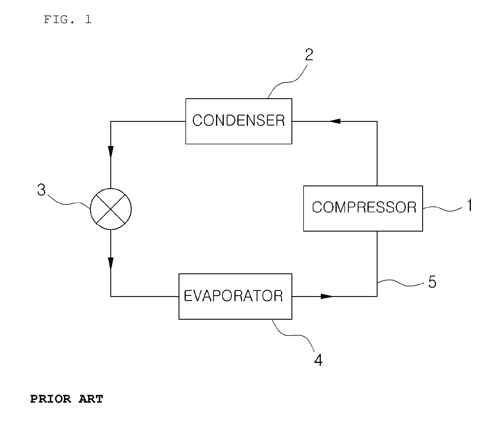
[0057]100: COMPRESSOR

[0058]200: CONDENSER

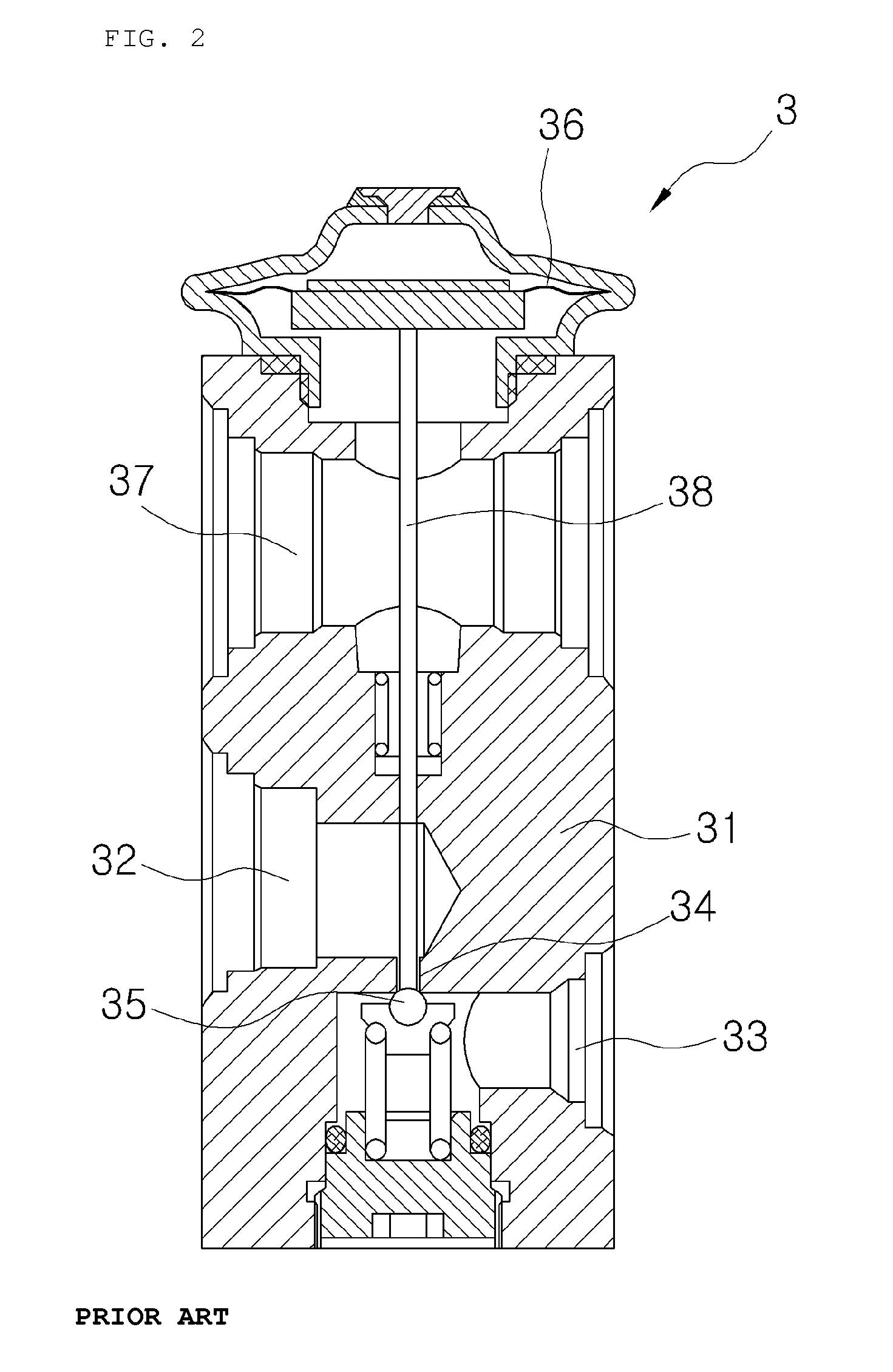
[0059]300: EXPANSION UNIT (300A: FIRST EXPANSION VALVE, 300B: SECOND EXPANSION VALVE, 300C: THIRD EXPANSION VALVE, 300D: DECOMPRESSING UNIT, 300E: SINGLE EXPANSION VALVE)

[0060]301: MAIN BODY

[0061]310: INLET

[0062]320: FIRST SUPPLY PASSAGE

[0063]321: FIRST SPACE PART

[0064]322: FIRST GUIDE PART

[0065]323: FIRST COMMUNICATING HOLE

[0066]324: FIRST INLET

[0067]325: THIRD SPACE PART

[0068]326: THIRD GUIDE PART

[0069]327: THIRD COMMUNICATING HOLE

[0070]328: THIRD OUTLET

[0071]330: SECOND SUPPLY PASSAGE

[0072]331: SECOND SPACE PART

[0073]332: SECOND GUIDE PART

[0074]333: SECOND COMMUNICATING HOLE

[0075]334: SECOND OUTLET

[0076]335: ORIFICE

[0077]336: FOURTH OUTLET

[0078]340: DISCHARGE PASSAGE

[0079]350: POWER ELEMENT

[0080]351: WORKING UNIT

[0081]352: DIAPHRAGM

[0082]360: CONTROL UNIT

[0083]361: ROD

[0084]362: BALL

[0085]370: ELASTIC UNIT

[0086]400: EVAPORATOR

[0087]410: FIRST EVAPORATING UNIT

[0088]420: SECOND EVA...


PUM


Abstract

Provided is a refrigerant cycle of an air conditioner for vehicles, and more particularly, a refrigerant cycle of an air conditioner for vehicles having a first evaporating unit and a second evaporating unit disposed upstream and downstream in a direction in which air blown from a single blower flows to control an amount of the refrigerant supplied to each evaporating unit, thereby making it possible to obtain optimal radiating performance (cooling performance) and cooling efficiency (COP) through the design of the optimal refrigerant flow ratio depending on the cooling load.

Description

TECHNICAL FIELD[0001]This document relates to a refrigerant cycle of an air conditioner for vehicles, and more particularly, to a refrigerant cycle of an air conditioner for vehicles having a first evaporating unit and a second evaporating unit disposed upstream and downstream in a direction in which air blown from a single blower flows to control an amount of refrigerant supplied to each evaporating unit, thereby making it possible to obtain optimal radiating performance (cooling performance) and cooling efficiency (COP) through the design of the optimal refrigerant flow ratio depending on the cooling load.BACKGROUND ART[0002]An air conditioner for vehicles is an apparatus embedded in a car in order to cool or heat the inside of a car in summer or winter or secure a front and back view of a driver by defrosting a windshield, or the like, in rainy weather or in winter. Generally, the air conditioner has both a heating system and a cooling system to selectively intake outside air or ...

Claims


Application Information

Patent Timeline
Patent Type & Authority Patents(United States)
IPC IPC(8): F25B39/02B60H1/32F25B5/02F25B41/06
CPCF25B5/02F25B41/062B60H1/323F25B2341/0683F25B41/335
Inventor AHN, YONG NAMPARK, TAE YOUNGJEE, YONG JUNJEONG, JAE WONMIN, EUN GILEE, HAE JUN
Owner HANON SYST
Why Eureka
Try Eureka