Oil cooling system

An oil cooling system and coolant technology, applied in the direction of gear lubrication/cooling, transmission parts, components with teeth, etc., can solve problems such as increased power loss, increased radiator pressure drop, secondary heating, etc., to avoid Pressure drop, avoidance of elevation, effect of simplified structure

Active Publication Date: 2014-12-10
ANHUI JIANGHUAI AUTOMOBILE GRP CORP LTD
View PDF6 Cites 5 Cited by
  • Summary
  • Abstract
  • Description
  • Claims
  • Application Information

AI Technical Summary

Problems solved by technology

This part of the heat is enough to make the lubricating fluid absorb and heat up to 120 degrees or even higher. If it is not cooled effectively, it will cause the lubricating oil to deteriorate, until the lubricating oil is oxidized at high temperature, the viscosity drops sharply, the lubricating effect becomes poor, and the oil vapor A variety of faults such as ejection from the air vent, burning of clutch or brake friction plates, etc., will eventually increase power loss and affect the life of the transmission
[0005] In the prior art, it is necessary to separately set up a complete set of oil cooling system for these hydraulic actuators that generate a lot of heat, such as adding additional oil temperature sensors, valves, radiators, etc. to the oil circulation circuit of the automatic transmission, which makes the oil cooling system very Complicated and additional valves will increase the pressure drop of the radiator and reduce the flow rate of the radiator per unit time, resulting in secondary heat generation, which will lead to premature deterioration of the automatic transmission oil, and may also lead to unstable performance of the lock-up clutch

Method used


Image

  • Oil cooling system
  • Oil cooling system
  • Oil cooling system

Examples


Embodiment Construction

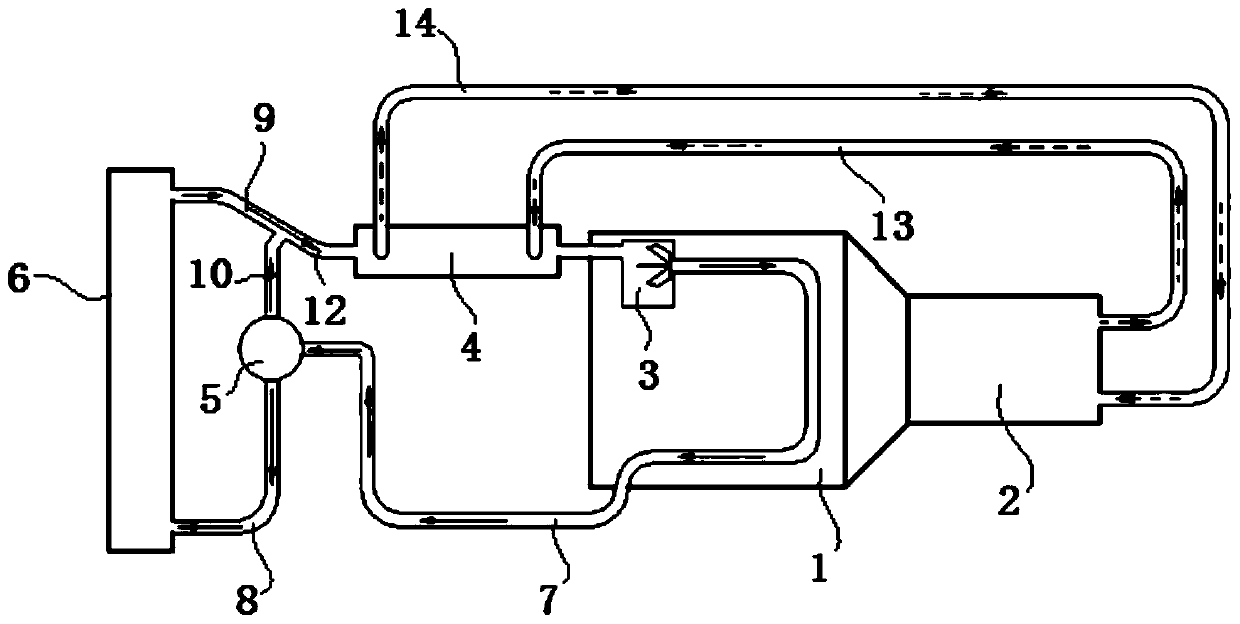
[0033] In the following description, the flow direction of coolant is represented by a solid line with arrows, and the flow direction of oil is represented by a dotted line with arrows. Moreover, although the following embodiments are described by taking an automatic transmission as an example, the described oil cooling system can also be applied to hydraulic actuators such as hydraulic retarders that require heat dissipation.

[0034] refer to figure 1, In the first embodiment, the oil cooling system includes the coolant circulation circuit of the engine, the oil circulation circuit of the hydraulic actuator and the oil cooler 4 . Specifically, in the coolant circulation circuit of the engine, the pump 3 provides flow power for the coolant, the coolant flows in the engine 1 to absorb heat, and then enters the oil cooler 4 through the pipeline 7, and the oil cooler 4 completes and After the heat exchange of the oil, the coolant enters the thermostat 5 through the pipeline 11 ...


PUM


Abstract

The invention provides an oil cooling system. The oil cooling system comprises a cooling liquid circulating loop of an engine and an oil circulating loop of a hydraulic execution mechanism and further comprises an oil cooler, and heat exchange is carried out on cooling liquid in the cooling liquid circulating loop of the engine and oil in the oil circulating loop of the hydraulic execution mechanism in the oil cooler. The oil cooling system is simple in structure, and pressure is reduced.

Description

technical field [0001] The invention relates to a cooling system for an engine and a hydraulic actuator. Background technique [0002] With the rapid development of the automobile industry and the improvement of people's requirements for driving comfort, hydraulic actuators are widely used, such as hydraulic retarders and automatic transmissions with variable speed and torque by hydraulic torque converters. These hydraulic actuators are used in Heat is generated during operation. [0003] The hydraulic retarder plays the role of auxiliary braking. The hydraulic retarder converts the kinetic energy of the vehicle into heat energy during work, and the heat energy needs to be dissipated as soon as possible. [0004] The development of automatic transmissions is constantly improving towards the direction of simplifying vehicle operation and improving vehicle comfort. The research and development of automatic transmissions is not only the research focus of current vehicle transm...

Claims


Application Information

Patent Timeline
IPC IPC(8): F16H57/04
CPCF16H57/0413F16H2700/00
Inventor 张荣瑾王凯峰李喜鹏张纬苏张翔
Owner ANHUI JIANGHUAI AUTOMOBILE GRP CORP LTD
Why Eureka
Try Eureka