A direct contact phase change heat storage device

A heat storage device and phase change heat storage technology, which is applied in the direction of heat storage equipment, indirect heat exchangers, heat exchanger types, etc. Small contact area, affecting heat storage or heat release performance, etc., to achieve the effect of improving heat storage and heat release performance, simple and reliable installation and use, and low production cost

Inactive Publication Date: 2017-06-27
邹杰
View PDF4 Cites 3 Cited by
  • Summary
  • Abstract
  • Description
  • Claims
  • Application Information

AI Technical Summary

Problems solved by technology

[0003] Because the volume of general substances will change significantly when the phase transition occurs, when the phase transition occurs in the fixed container, the substance will not be in close contact with the side wall of the fixed container, resulting in poor heat transfer effect, thus affecting heat storage or exothermic properties
[0004] Instead of using a fixed container, due to the effect of the surface tension of the heat storage material, the contact area between the heat transfer fluid and the heat storage material is small, which also affects the heat storage or heat release performance.

Method used


Image

  • A direct contact phase change heat storage device
  • A direct contact phase change heat storage device

Examples


Embodiment 1

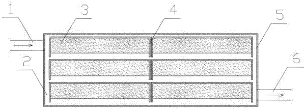
[0011] The structure diagram of the present invention is as figure 1 As shown, the direct contact phase-change heat storage device of the present invention includes a heat-carrying fluid inlet 1, a heat-carrying fluid flow channel 2, a phase-change heat storage material 3, a fixed frame 4 of a heat-change material, and a heat storage device container shell 5. Heat-carrying fluid outlet 7, in which several phase-change heat storage material fixing frames 4 are installed in the heat storage device container shell 5, between adjacent phase-change heat storage material fixing frames 4 and phase change heat storage material fixing frames 4 The gap between the heat storage device container shell 5 is the heat carrier fluid flow channel 2, the phase change heat storage material 3 is installed in the phase change heat storage material fixed frame 4, and one end of the heat storage device container shell 5 is provided with a heat carrier The fluid inlet 1 and the other end of the heat ...

Embodiment 2

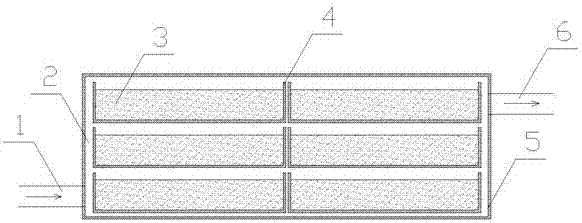
[0022] The structure diagram of the present invention is as figure 2 As shown, the difference between the present invention and Embodiment 1 is that the density of the phase-change heat storage material 3 is higher than that of the heat-carrying fluid, and the opening direction of the heat storage material fixing frame 4 is upward, and the phase-change heat storage material 3 is subjected to gravity, and there is a direction to force to move. Under the constraint of the closed end of the heat storage material fixed frame 4, the phase change heat storage material 3 is stored in the heat storage material fixed frame 4, such as figure 2 shown.

[0023] In the present invention, when heat storage is required, the heat-carrying fluid inlet 1 flows into the high-temperature heat-carrying fluid, and in the process of passing through the heat-carrying fluid channel 2, the heat is transferred to the phase-change heat storage material 3 and the heat storage material fixed frame 4, an...


PUM


Abstract

The invention relates to a direct contact phase-changing heat storage device. The direct contact phase-changing heat storage device comprises a heat transfer fluid inlet (1), heat transfer fluid runners (2), phase-changing heat storage materials (3), phase-changing heat storage material fixing frames (4), a heat storage device container shell (5) and a heat transfer fluid outlet (7), wherein the multiple phase-changing heat storage material fixing frames (4) are mounted in the heat storage device container shell (5); gaps between the adjacent phase-changing heat storage material fixing frames (4) as well as between the phase-changing heat storage material fixing frames (4) and the heat storage device container shell (5) are the heat transfer fluid runners (2); the phase-changing heat storage materials (3) are placed in the phase-changing heat storage material fixing frames (4); the heat transfer fluid inlet (1) is formed in one end of the heat storage device container shell (5), and the heat transfer fluid outlet (7) is formed in the other end of the heat storage device container shell (5); and the heat transfer fluid inlet (1) and the heat transfer fluid outlet (7) are used for allowing heat transfer fluid to flow in and flow out respectively. The direct contact phase-changing heat storage device is large in heat storage density, simple in structure, good in heat exchange effect, wide in application range, reliable in performance and low in manufacturing cost.

Description

technical field [0001] The invention is a direct contact phase change heat storage device, which belongs to the innovative technology of the phase change heat storage device. Background technique [0002] The phase change heat storage device utilizes the characteristics of certain materials that can store and release a large amount of heat energy during phase change, stores the heat energy, and releases the heat energy when needed. [0003] Since the volume of a general substance will change significantly when a phase transition occurs, when a phase transition occurs in a fixed container, the substance will not be in close contact with the side wall of the fixed container, resulting in a problem of poor heat transfer effect, thereby affecting heat storage or exothermic properties. [0004] Instead of using a fixed container, due to the effect of the surface tension of the heat storage material, the contact area between the heat transfer fluid and the heat storage material i...

Claims


Application Information

Patent Timeline
Patent Type & Authority Patents(China)
IPC IPC(8): F28D20/02
CPCF28D20/025Y02E60/14
Inventor 罗晋湘张圆明邹杰
Owner 邹杰
Why Eureka
Try Eureka