
Electron source, X ray source and device using X ray source

An electron source and X-ray technology, which is applied in the field of X-ray sources, can solve the problems of affecting emission efficiency, waste of electron emission sources, and insufficient emission current intensity, and achieve the effect of reducing radiation dose and reducing exposure

Active Publication Date: 2016-03-02
NUCTECH CO LTD
View PDF22 Cites 4 Cited by
  • Summary
  • Abstract
  • Description
  • Claims
  • Application Information

AI Technical Summary

Problems solved by technology

Its technical feature of setting anti-charging film on the surface of the gate isolation makes the electron emission device effectively prevent sparking, but its linear and long electron emission source only produces electron emission at the place where the gate has an opening. The position blocked by the pole bridge cannot produce electron emission, and the electron emission source is wasteful. At the same time, its structural size is not optimized. The current intensity is still not high enough

Method used


Image

  • Electron source, X ray source and device using X ray source
  • Electron source, X ray source and device using X ray source
  • Electron source, X ray source and device using X ray source

Examples


specific approach 1

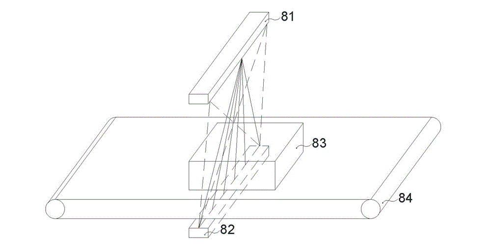
[0144] Specific scheme 1: There is one X-ray source, the X-ray source has an electron emission area to form an X-ray target point, and there are multiple detectors, forming a linear array or a planar array (also can be a planar detector). Some X-ray perspective imaging systems have a similar composition structure. The solution has simple structure, small volume and low cost, but the field emission X-ray source of the present invention has the advantages of low control voltage and fast starting speed.

specific approach 2

[0145] Specific plan two: one X-ray source, the X-ray source has two electron emission regions, the target materials of the two targets are different, and can alternately generate two X-ray beams with different energies, and there are multiple detectors to form a linear Arrays or planar arrays (also planar detectors), or further dual-energy detectors. The solution is simple in structure, small in size and low in cost. At the same time, through dual-energy imaging, the material identification ability of the detection object is increased.

specific approach 3

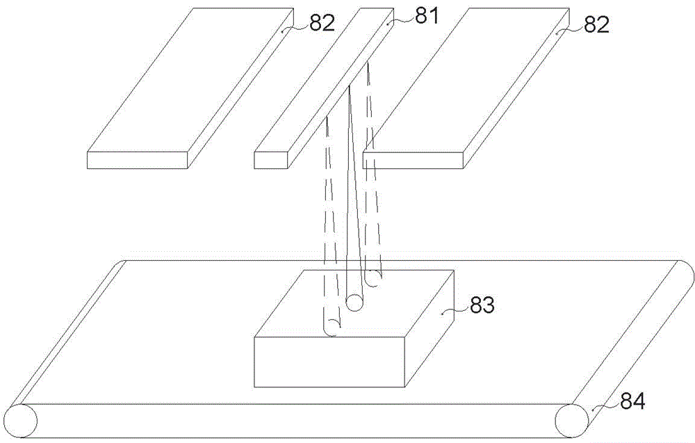
[0146] Specific scheme three: the X-ray source is a distributed X-ray source, the X-ray source has multiple X-ray targets, and multiple detectors, forming a linear array or a planar array (or a planar detector). Multiple target points perform perspective imaging on the detected object through different angles (positions), and finally a perspective image with multi-level information in the depth direction can be obtained. Compared with the multi-view system using multiple common X-ray sources, this scheme has a simple structure. Small size and low cost.

[0147] Specific solution 4: The X-ray source is a distributed X-ray source with multiple X-ray targets and one or a few detectors. Through the "reverse" imaging principle, a perspective image is obtained. The feature of this solution is that the number of detectors is reduced and the cost is reduced.


PUM


Abstract

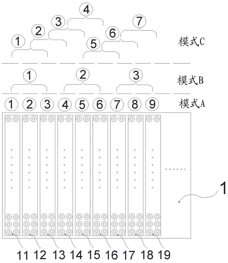
The invention relates to an electron source and an X ray source using the electron source. The electron source is provided with at least two electron emission regions; each electron emission region is provided with multiple micro electron emission units; each micro electron emission unit comprises a base layer, an insulated layer located on the base layer, a gate layer located on the insulated layer, an opening located in the gate layer and an electron emitter fixed on the base layer and corresponding to the opening; the micro electron emission units in the same electron emission region are electrically connected for emitting electrons at the same time or not emitting electrons at the same time, and different electron emission regions are electrically isolated.

Description

technical field [0001] The present invention relates to an electron source for generating electron beams and an X-ray source for generating X-rays using the electron source, in particular to an electron source for generating electron beams from different positions in a predetermined manner and an X-ray source for generating X-rays in a predetermined manner from different positions X-ray source and equipment using the X-ray source. Background technique [0002] Electron sources refer to equipment or components that can generate electron beams. Commonly used names include electron guns, cathodes, emitters, etc. Electron sources are widely used in display devices, X-ray sources, microwave tubes, etc. The X-ray source refers to the equipment that generates X-rays. The core is the X-ray tube, which is composed of an electron source, an anode, and a vacuum-sealed casing, and usually includes auxiliary devices such as power supply and control system, cooling, and shielding. X-ray ...

Claims


Application Information

Patent Timeline
Patent Type & Authority Applications(China)
IPC IPC(8): H01J35/02H01J35/08H01J35/32
CPCH01J3/021H01J2203/022H01J2203/0224H01J2203/0236H05G1/52H01J2235/068H01J35/065H01J35/14H01J35/147H05G1/06H01J35/116H01J2201/30469H01J2235/062H01J35/02
Inventor 唐华平陈志强李元景王永刚秦占峰
Owner NUCTECH CO LTD
Learn More