Light emitting device and display device using the light emitting device

A light-emitting device and a technology of a light-emitting material layer, applied in nanotechnology, optics, light guides, etc. for materials and surface science, can solve the problems of reducing display brightness, wasting electric energy, and losing light intensity, and achieve the effect of simple structure

Active Publication Date: 2018-05-01
TSINGHUA UNIV +1
View PDF5 Cites 0 Cited by
  • Summary
  • Abstract
  • Description
  • Claims
  • Application Information

AI Technical Summary

Problems solved by technology

Since the general light source emits non-polarized light, it means that at least half of the light intensity will be lost through the polarizer, which not only reduces the display brightness but also wastes electric energy

Method used


Image

  • Light emitting device and display device using the light emitting device
  • Light emitting device and display device using the light emitting device
  • Light emitting device and display device using the light emitting device

Examples


Embodiment Construction

[0033] The light-emitting device provided by the present invention and the display device adopting the light-emitting device will be described in further detail below in conjunction with the drawings and specific embodiments. The light-emitting devices provided by the first to fourth embodiments of the present invention are light-pumped light-emitting devices, which are excited by external light to emit light. The light-emitting devices provided by the fifth to eighth embodiments of the present invention are electrically pumped light-emitting devices, which are excited by electric energy to emit light. The display device using the light-emitting device is a liquid crystal display.

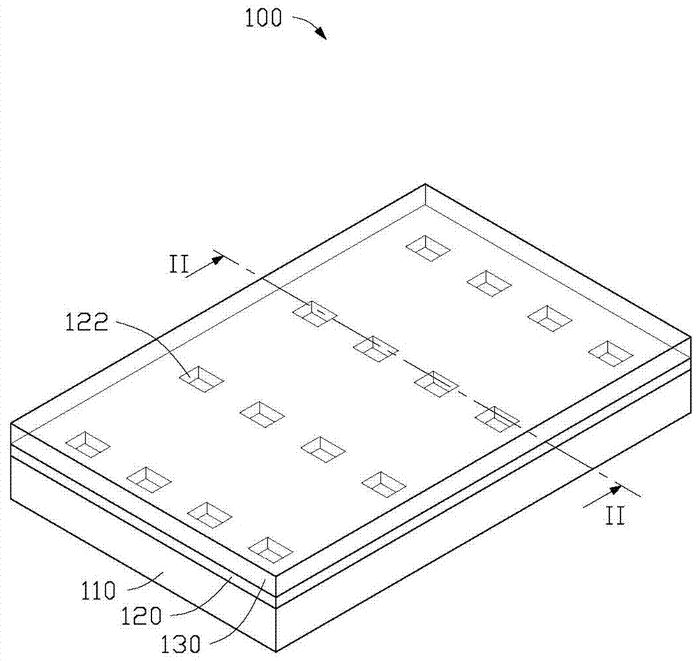
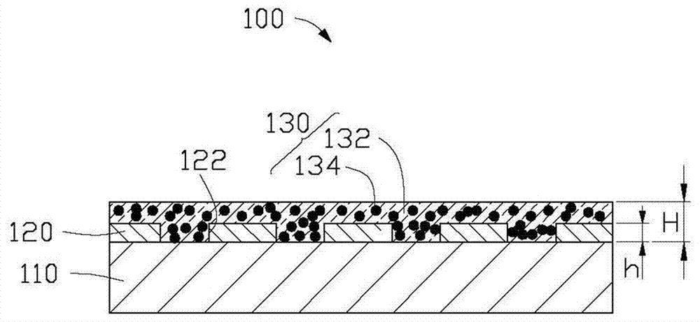
[0034] See Figure 1-2 The first embodiment of the present invention provides a light emitting device 100, which includes an insulating transparent substrate 110, a metamaterial layer 120, and a light emitting material layer 130. The insulating transparent substrate 110, the metamaterial layer 120, a...


PUM

PropertyMeasurementUnit
thicknessaaaaaaaaaa
widthaaaaaaaaaa
thicknessaaaaaaaaaa

Abstract

The disclosure relates to a light emitting device. The light emitting device includes an insulative transparent substrate, a light emitting material layer, and a metal metamaterial layer. The metal metamaterial layer is located between the insulative transparent substrate and the light emitting material layer. The metal metamaterial layer includes a number of periodically aligned metamaterial units. Because the plasmon of the metamaterial can control electromagnetic properties in nanoscale, light from the light emitting device can be polarized in nanoscale. Thus, the light emitting device can emit polarized light. The display device using the light emitting device is also provided.

Description

Technical field [0001] The invention relates to a light-emitting device and a display device using the light-emitting device, in particular to a metamaterial plasmon integrated light-emitting device and a display device using the light-emitting device. Background technique [0002] Currently, liquid crystal displays have been widely used. The principle adopted by the liquid crystal display is to use an electrical modulation layer, such as liquid crystal molecules, to change the polarization of incident polarized light, so that the light intensity that finally passes through the analyzer changes. [0003] In order to generate polarized light, the currently widely used method is to use thin-film polarizers to polarize the light from the light source (tube or LED). Since the general light source emits unpolarized light, this means that at least half of the light intensity is lost through the polarizer, which not only reduces the display brightness but also wastes electrical energy. ...

Claims


Application Information

Patent Timeline
Patent Type & Authority Patents(China)
IPC IPC(8): H01L33/44H01L33/42G02F1/13357
CPCG02B1/002B82Y20/00B82Y30/00C09K19/52C09K2219/00G02B5/008G02B5/30G02B6/0066
Inventor 任梦昕李群庆张立辉陈墨范守善
Owner TSINGHUA UNIV
Why Eureka
Try Eureka