
A fiber cooling head suitable for high power semiconductor laser fiber coupling modules

A fiber coupling and semiconductor technology, applied in the field of laser technology, can solve the problems of user passiveness, low module integration, long cycle, etc., and achieve the effects of low cooling water requirements, easy integration and miniaturization, and simple structure

Active Publication Date: 2018-10-23
JIANGXI LIANOVATION NEW LIGHT COLLABORATIVE INNOVATION
View PDF5 Cites 0 Cited by
  • Summary
  • Abstract
  • Description
  • Claims
  • Application Information

AI Technical Summary

Problems solved by technology

[0004] (1) The optical fiber cooling head is generally an independent procurement unit with independent water flow, which is similar to an external device, resulting in low integration with the module
[0005] (2) Once a problem occurs, the user is very passive
Due to the technical protection of foreign companies, it cannot be repaired in China and must be returned to the original factory for repairs, which takes a long time.

Method used


Image

  • A fiber cooling head suitable for high power semiconductor laser fiber coupling modules
  • A fiber cooling head suitable for high power semiconductor laser fiber coupling modules
  • A fiber cooling head suitable for high power semiconductor laser fiber coupling modules

Examples


Embodiment 1

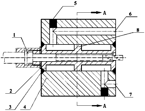
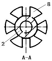
[0023] Such as figure 1 The optical fiber cooling head and the module shown are integrated processing, and the fiber cooling head waterway is fixed to the module shell with threads, and the waterway interface matching the cooling head water inlet and water outlet is left on the module shell, the fiber optic cooling head waterway and the module waterway Tightly connected through the waterproof pressure ring. The cooling water first flows through the water channel of the module to cool the laser chip, then enters the inner cavity of the cooling head through the water inlet, flows through the heat dissipation channel in the inner cavity to cool the target optical fiber, and finally returns the water to the cooling water return channel of the fiber coupling module through the water outlet, and completes the process. For the cooling of lasers and optical fibers in the system, this method makes the system more compact and simple.

Embodiment 2

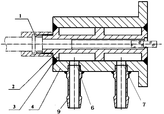
[0025] combine figure 2 This embodiment will be described. The difference between this embodiment and Embodiment 1 is that in this embodiment, the optical fiber cooling head is passed through water alone, and can be used as a component alone, and has lower requirements on the cooling water used. The faucet of this solution is set on the water inlet and the water inlet, and adopts quick-connect joints, which are easy to transfer quickly.


PUM


Abstract

The invention provides an optical fibre cooling head suitable for a high-power semiconductor laser optical fibre coupling module. In the scheme, the optical fibre cooling head comprises an outer cylinder and a cavity sleeving in the outer cylinder; the cavity comprises a support part and an axial centre; the support part is arranged outside the axial centre and connected with the inner wall of the outer cylinder; the axial centre is a hollow channel; a coupled optical fibre is arranged in one end of the axial centre; an optical fibre joint is arranged at the other end of the axial centre; the area between the axial centre and the outer cylinder is a heat dissipation channel; the direction of the heat dissipation channel is the same to that of the coupled optical fibre; and a water inlet and a water outlet communicated with the heat dissipation channel are arranged on the outer cylinder. The optical fiber cooling head in the scheme provided by the invention has the advantages of being compact in structure, high in flexibility and integration level and easy to maintain and replace.

Description

technical field [0001] The invention relates to the application field of laser technology, in particular to an optical fiber cooling head suitable for high-power semiconductor laser optical fiber coupling modules. Background technique [0002] Due to the advantages of high electro-optical efficiency, small size, high reliability, and low cost, semiconductor lasers have obvious application advantages in material processing, biomedicine, military defense, and pumping solid-state lasers, and have developed rapidly in recent years. Widely used, especially high-brightness, high-power fiber-coupled output semiconductor laser as the pump source of fiber laser, its performance level restricts the power output of fiber laser, therefore, research on high-reliability high-power fiber-coupled output semiconductor laser for high-energy fiber The development of lasers is of great significance. [0003] In the fiber coupling output system, the power density of the fiber coupling end is ex...

Claims


Application Information

Patent Timeline
Patent Type & Authority Patents(China)
IPC IPC(8): H01S3/04H01S3/067H01S3/0941
CPCH01S3/0407H01S3/067H01S3/0941
Inventor 张凯吴华玲郭林辉余俊宏高松信武德勇
Owner JIANGXI LIANOVATION NEW LIGHT COLLABORATIVE INNOVATION
Learn More