Radio frequency laser with cylindrical surface collimating mirror

A technology of collimating mirrors and lasers, which is applied in the field of radio frequency lasers, can solve the problems of wasting laser energy, increasing processing costs, and reducing the service life of lasers, and achieves the effects of reducing processing costs, prolonging service life, and improving laser processing effects

Inactive Publication Date: 2016-03-02
BEIJING RECI LASER TECH
View PDF5 Cites 1 Cited by
  • Summary
  • Abstract
  • Description
  • Claims
  • Application Information

AI Technical Summary

Problems solved by technology

[0004] (1) The laser spot (beam cross-section) is flat, similar to a flat ellipse. This kind of beam affects the application of laser processing. The engraving pattern is fuzzy and not detailed. Doesn't work well, other apps don't work well
[0005] (2) For this kind of flat laser beam, the laser energy is scattered and not concentrated, which reduces the utilization rate of laser energy and wastes part of the laser energy
[0006] (3) In order to offset the wasted laser energy, the laser power must be increased during processing, which increases the processing cost and reduces the service life of the laser

Method used


Image

  • Radio frequency laser with cylindrical surface collimating mirror
  • Radio frequency laser with cylindrical surface collimating mirror

Examples


Embodiment Construction

[0021] A radio frequency laser installed with a cylindrical collimator mirror according to an exemplary embodiment of the present invention will be described in detail below with reference to the accompanying drawings.

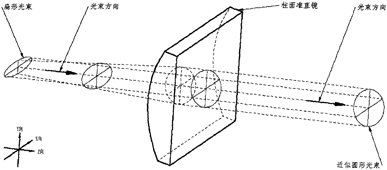
[0022] like figure 1 As shown, the laser beam is output from the laser cavity through the laser output window. At this time, the laser beam is flat, and its characteristic is that the beam divergence angle in the long direction is close to zero, and the beam divergence angle in the flat direction is obvious. On the optical path of the laser beam, When the flat beam diverges to be approximately equal to the long beam, this position is the best position for the cylindrical collimator to shape the laser beam. The shaped laser beam is approximately circular, and the beam is output in parallel.

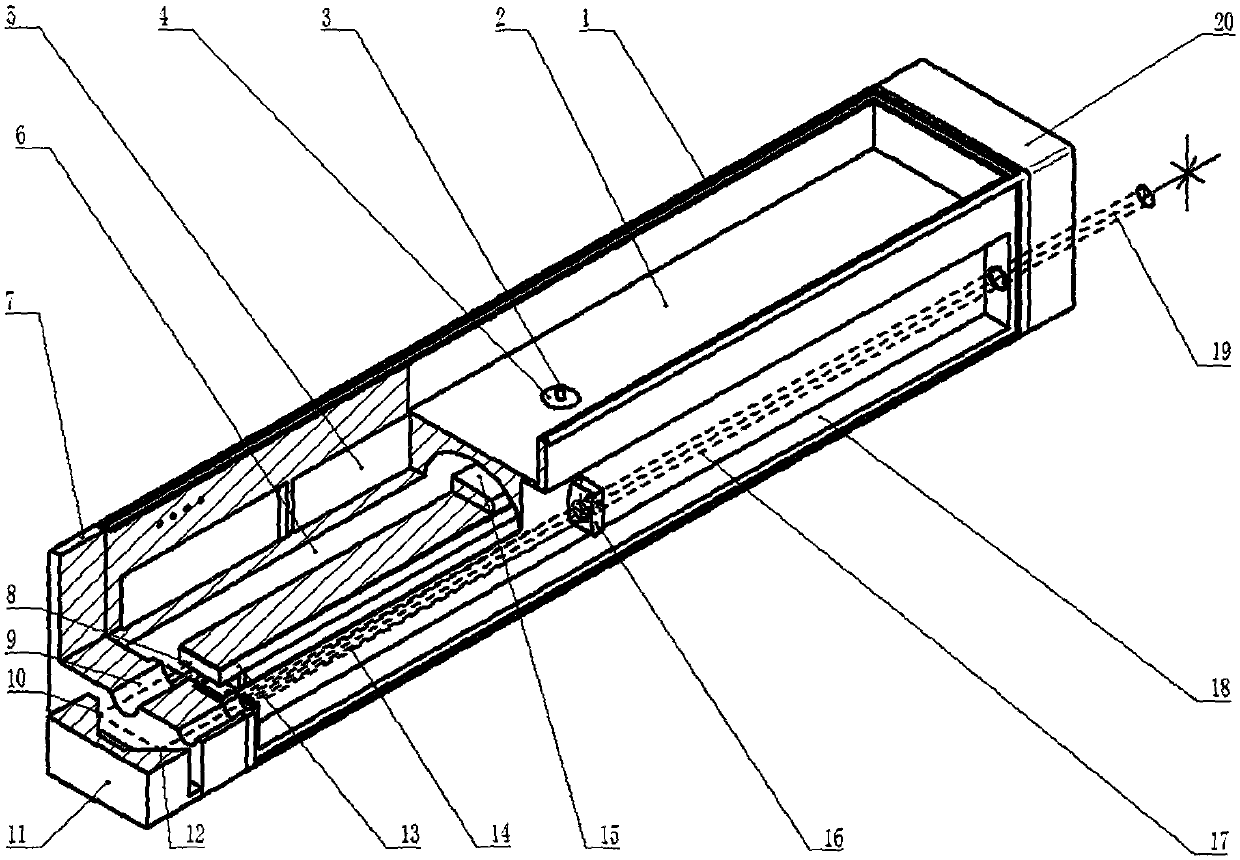
[0023] figure 2 An axonometric view of a radio frequency laser mounted with a cylindrical collimating mirror is shown according to an example embodiment of the present ...


PUM


Abstract

The invention provides a radio frequency laser with cylindrical surface collimating mirror, mainly comprising a radio frequency laser, a cylindrical surface collimating mirror and a reflex lens.

Description

technical field [0001] The invention relates to a radio frequency laser, in particular to a radio frequency laser equipped with a cylindrical collimating mirror. Background technique [0002] None of the conventional radio frequency lasers currently on the market is equipped with a cylindrical collimator. [0003] Radio frequency lasers without cylindrical collimating mirrors mainly have the following defects: [0004] (1) The laser spot (beam cross-section) is flat, similar to a flat ellipse. This kind of beam affects the application of laser processing. The engraving pattern is fuzzy and not detailed. Doesn't work well, and other apps don't work well either. [0005] (2) For this kind of flat laser beam, the laser energy is scattered and not concentrated, which not only reduces the utilization rate of laser energy, but also wastes part of the laser energy. [0006] (3) In order to offset the wasted laser energy, the laser power must be increased during processing, which...

Claims


Application Information

Patent Timeline
Patent Type & Authority Applications(China)
IPC IPC(8): H01S3/081H01S3/02
Inventor 赖颢天
Owner BEIJING RECI LASER TECH
Why Eureka
Try Eureka