Supercharge Your Innovation With Domain-Expert AI Agents!

Riser flow control

A standpipe and pressure control technology, applied in the field of fluid devices, can solve the problems of reduced controllability of slurry flow and achieve the effect of improving pressure control

Inactive Publication Date: 2016-03-02
IHC HOLLAND NV
View PDF9 Cites 3 Cited by
  • Summary
  • Abstract
  • Description
  • Claims
  • Application Information

AI Technical Summary

Problems solved by technology

Free gas can cause problems with the function of certain devices in the standpipe, such as centrifugal pumps, and also leads to less controllable slurry flow as the slurry velocity increases and fluctuates as the gas expands

Method used


Image

  • Riser flow control
  • Riser flow control
  • Riser flow control

Examples


Embodiment Construction

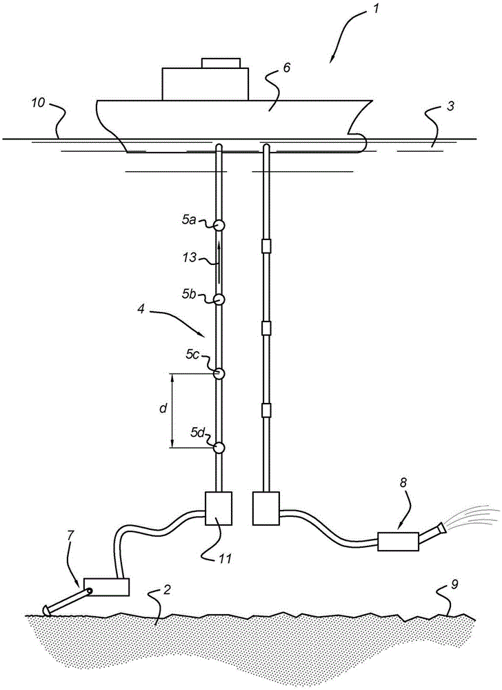
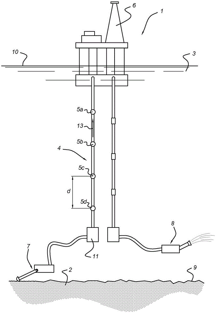
[0047] figure 1 A deep sea mining system 1 for use in a deep sea mining method is shown. The extraction system 1 comprises an excavation system 7 for excavating material 2 at the bottom 9 of a body of water 3 . The excavation system 7 has a boom member provided at its lower end with a cutting member. The excavation system 7 may be supported by the bottom 9 in a floating or rolling manner.

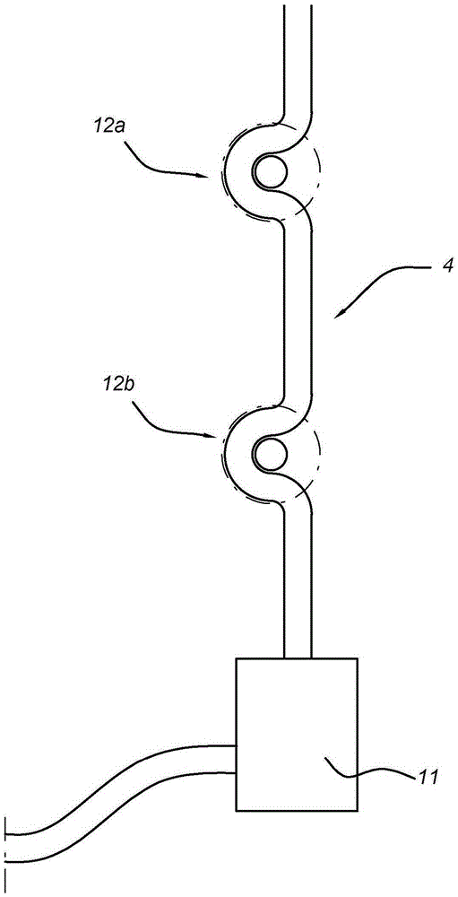
[0048] The production system 1 comprises a riser system 4 for transporting a slurry 13 of matter and water from the bottom 9 of the body of water upwards to a slurry handling base 6 . The riser system 4 includes adjustable pump means 11 adjacent to the bottom 9 of the body of water for pressurized delivery of slurry 13 . The base 6 is, for example, a floating vessel ( figure 1 ) or floating platform ( figure 2 ) or a fixed platform (not shown).

[0049] The production system 1 includes pressure control devices 5a, 5b, 5c, 5d for maintaining a controlled riser system pressure within the...


PUM


Abstract

Deep sea mining method comprising: excavating matter (2), which may comprise gashydrates, at a bottom (9) of a body of water (3); operating a riser system (4) for transporting a slurry (13) of matter and water; transporting the slurry from the bottom of a body of water upwards to a slurry processing base (6); and maintaining a controlled riser system pressure, higher than the environmental pressure, inside the riser system for avoiding forming or release of gas and expanding of gas contained in the slurry during transporting the slurry.

Description

Background technique [0001] The present invention relates to a deep sea mining method, the method comprising: [0002] - excavate material from the bottom of a body of water, [0003] - operating riser systems for the transport of slurries of matter and water, [0004] - Conveying the slurry from the bottom of the water body up to the slurry handling base. [0005] EP2570340 relates generally to a device for capturing lighter-than-water fluids escaping from subsea sources. The unit is used to collect and temporarily store oil and / or gas escaping from uncontrolled deep sea boreholes. EP2570340 aims to provide an improved device for collecting and temporarily storing fluid ascending from a subsea source, particularly with respect to the device's ability to handle gas-containing fluids. EP2570340 discloses a standpipe having a flow restrictor, such as a chokedisk arranged inside the standpipe for restricting fluid flow. According to EP2570340, a gas-containing fluid can be t...

Claims


Application Information

Patent Timeline
Patent Type & Authority Applications(China)
IPC IPC(8): E21B17/01E21C50/00E02F3/88E02F3/90E02F7/06
CPCE02F3/8866E02F3/90E02F3/907E02F7/065E21C50/00E21B17/01E21B17/015E02F3/905
Inventor 约翰内斯·巴托洛梅乌斯·范 杜斯堡皮耶特·亚伯拉罕·卢西埃尔
Owner IHC HOLLAND NV
Features
  • R&D
  • Intellectual Property
  • Life Sciences
  • Materials
  • Tech Scout
  • Unparalleled Data Quality
  • Higher Quality Content
  • 60% Fewer Hallucinations
Learn More