Clamping and positioning device for pneumatic flange

A technology for clamping and positioning and flanges, which is applied in positioning devices, clamping devices, clamping, etc., can solve problems such as prolonging processing time, destroying flange structures, and increasing processing procedures

Inactive Publication Date: 2016-03-09
CHONGQING SHUAICHANG MACHINE MFG
View PDF0 Cites 6 Cited by
  • Summary
  • Abstract
  • Description
  • Claims
  • Application Information

AI Technical Summary

Problems solved by technology

[0002] There is an existing flange, which is provided with reinforcing ribs for its strength, so the bolt connection holes need to be arranged between the reinforcing ribs, and it needs to be accurately positioned; the existing clamping and positioning method is, on the flange Scribe a line, and cut off a part of the flange through the scribed line, so that the flange forms an incomplete circle, thereby forming a positioning plane, and then cooperate with the outer circumference of the flange plate through the V-shaped positioning fork, a

Method used


Image

  • Clamping and positioning device for pneumatic flange
  • Clamping and positioning device for pneumatic flange
  • Clamping and positioning device for pneumatic flange

Examples


Embodiment 1

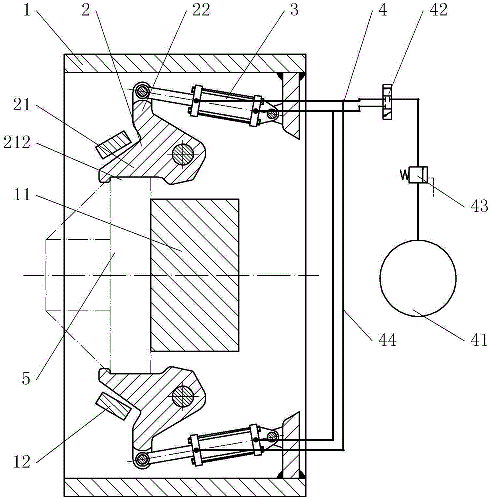
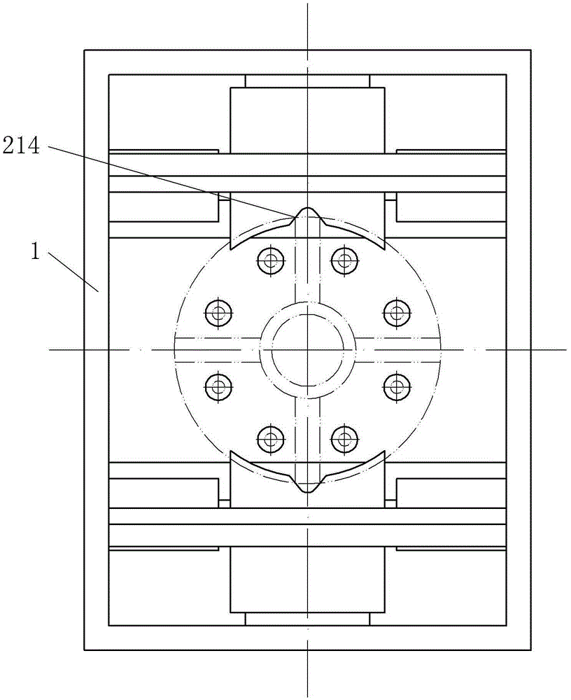
[0018] The embodiment is basically as attached figure 1 , figure 2 Shown: A pneumatic flange clamping and positioning device includes a clamping base 1, a clamping jaw 2, a driving cylinder 3 and a control system 4; the clamping base 1 is a square shell, and there are two clamping jaws 2. , And are symmetrically hinged in the inner cavity of the clamping seat 1. One end of the clamping jaw 2 is a clamping end 21, and the other end is a force end 22. The clamping end 21 has an arc-shaped clamping surface 211, The surface 211 has the same curvature as the outer circumference of the flange 5 to be clamped. The clamping surface 211 is perpendicular to the force-receiving end 22. On the left side of the clamping surface 211, there is also an arc-shaped protrusion 212. There is a limit gap 214 on the convex 212, and the two opposite sides of the limit gap 214 have a certain slope; the cylinder of the driving cylinder 3 is hinged in the inner cavity of the clamping seat 1, and the pis...

Embodiment 2

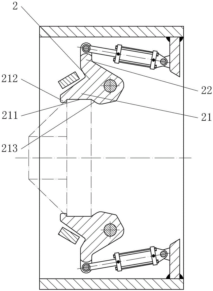
[0021] As attached image 3 As shown: the difference between the second embodiment and the first embodiment is that the limit block 11 is eliminated in the second embodiment, and a limit arc surface 213 is provided on the right side of the clamping surface 211 of the clamping jaw 2. The surface 213 is a circular arc surface with the same arc as the clamping surface 211. The limiting arc surface 213 and the clamping surface 211 form an included angle of 150°, and the limiting arc surface 213 protrudes outward relative to the clamping surface 211 to limit The distance from the intersection of the arc surface 213 and the clamping surface 211 to the intersection of the arc-shaped protrusion 212 and the clamping surface 211 is equal to the thickness of the flange 5.

[0022] During the clamping process, the two limiting arc surfaces 213 also rotate to the center at the same time, but due to the inclination between the limiting arc surface 213 and the clamping surface 211, the clamping...


PUM


Abstract

The invention discloses a clamping and positioning device for a pneumatic flange and relates to a flange clamp. The clamping and positioning device for the pneumatic flange comprises a clamping seat, clamping jaws, driving air cylinders and a control system. A clamping seat inner cavity is formed in the clamping seat. The two clamping jaws are symmetrically hinged to the clamping seat inner cavity. One ends of the clamping jaws are clamping ends, and the other ends of the clamping jaws are stress ends. The clamping ends are provided with circular-arc-shaped clamping faces. A circular-arc-shaped protrusion is arranged on the clamping face of the front end of each clamping jaw, and a limiting notch is formed in each circular-arc-shaped protrusion. Cylinder bodies of the driving air cylinders are hinged to the clamping seat, and piston rods are hinged to the stress ends of the clamping jaws. A control system is used for controlling the driving air cylinders, and a rear limiting part is arranged on the rear side of each clamping jaw. According to the clamping and positioning device, machining processes in the flange machining process can be reduced, and positioning and clamping of the flange can be achieved rapidly.

Description

Technical field [0001] The invention relates to a clamp, in particular to a flange clamp. Background technique [0002] There is a kind of flange, for its strength is provided with stiffeners, so the bolt connection holes need to be arranged between the stiffeners, and they need to be accurately positioned; the existing clamping and positioning method is on the flange Scribe, and cut off a part of the flange through the scribed line, so that the flange forms an incomplete circle, thus forming a positioning plane, and then match the outer periphery of the fara plate through the V-shaped positioning fork, and pass a The positioning block with a plane is matched with the positioning plane on the flange to realize the clamping of the flange, and the positioning of the flange is realized by the cooperation of the positioning block and the positioning plane; this method realizes the flange The clamping and positioning of the disc, but the flange disc needs to be scribed and cut, which...

Claims


Application Information

Patent Timeline
IPC IPC(8): B23Q3/00
CPCB23Q3/00B23Q2703/04B23Q2703/10
Inventor 龚立
Owner CHONGQING SHUAICHANG MACHINE MFG
Why Eureka
Try Eureka