A position correction device

A technology of a correction device and a limit device, which is applied in the direction of feeding devices, automatic control devices, manufacturing tools, etc., can solve problems such as deviations and work errors, improve processing accuracy, have strong versatility and economy, and shorten position adjustment time Effect

Active Publication Date: 2019-01-18
厦门厦芝科技工具有限公司
View PDF7 Cites 0 Cited by
  • Summary
  • Abstract
  • Description
  • Claims
  • Application Information

AI Technical Summary

Problems solved by technology

[0002] Floating tool holders are widely used in existing machine tools due to their self-centering advantages during work. However, since floating tool holders have a certain floating gap, when measuring workpieces clamped on floating tool holders in a static state , the center of the workpiece is often not located on the axis of the floating tool holder but is biased to one side of the floating tool holder, so when measuring the position of the workpiece relative to the machine tool, the floating gap will bring a certain deviation, especially for workpieces with angular parameters Such as tools, etc., resulting in inevitable errors in subsequent work

Method used


Image

  • A position correction device
  • A position correction device

Examples


Embodiment

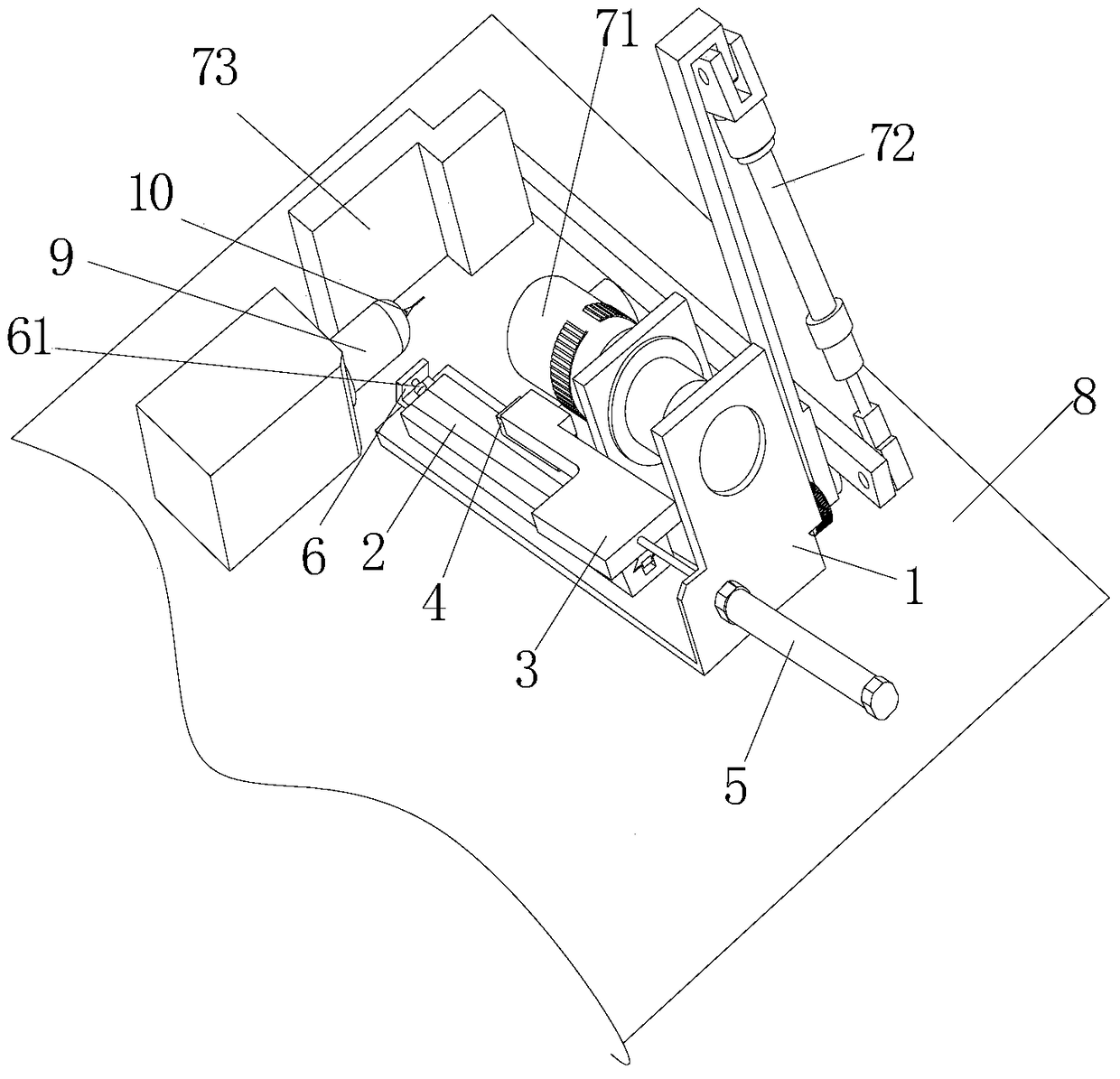
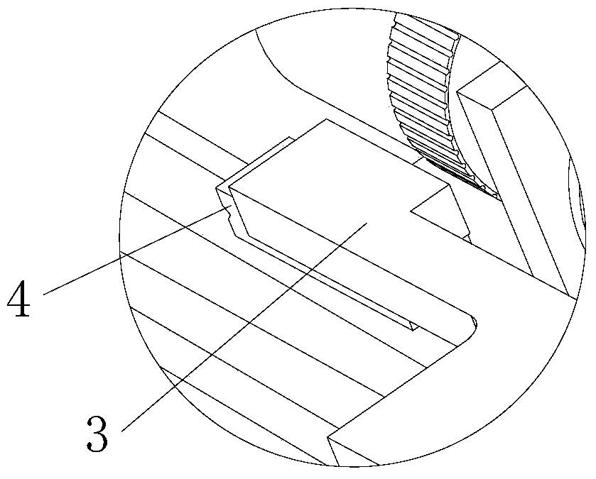
[0020] Such as figure 1 and figure 2 As shown, the position correction device is installed on the machine tool 8, and the position correction device includes a base 1, a guide rail 2 installed on the base 1, a sliding ejector rod 3 installed on the guide rail 2, and a front end of the sliding ejector rod 3 for moving the workpiece 10 Groove head 4 with the top offset from the center of the machining circle, a push rod 5 installed on the base 1 for pushing and pulling the sliding ejector rod 3 to slide along the guide rail 2, a limit device 6 installed at the front end of the guide rail 2, a workpiece angle imaging device and an information processing system .

[0021] Wherein: the guide rail 2 is a dovetail groove guide rail, and the sliding ejector rod 3 is installed on a sliding bearing adapted to the guide rail 2 to slide back and forth; the groove top 4 is a V-shaped block whose opening is parallel to the workpiece; the push rod 5 is adopted in this embodiment The cylin...


PUM


Abstract

The invention discloses a position correction device. The position correction device comprises a base installed on a machine tool, a deviation ejecting device installed on the base and used for ejecting a workpiece to make the workpiece deviate the axis of a floating tool handle, and a workpiece angle deviation rectification device controlled by a computer and capable of automatically obtaining and adjusting the angle of the workpiece. According to the position correction device, floating gaps caused by the floating tool handle when the workpiece is clamped each time can be effectively eliminated; errors of the follow-up work such as measuring and machining are reduced; the machining precision is greatly improved, and the position adjusting time of the workpiece with angle parameters is shortened during machining; in addition, the universality and economical efficiency of the position correction device are high, and the position correction device can assist in completing operations such as workpiece measuring and machining.

Description

technical field [0001] The invention relates to a position correcting device, in particular to a position correcting device capable of eliminating errors caused when a floating tool handle clamps a workpiece. Background technique [0002] Floating tool holders are widely used in existing machine tools due to their self-centering advantages during work. However, since floating tool holders have a certain floating gap, when measuring workpieces clamped on floating tool holders in a static state , the center of the workpiece is often not located on the axis of the floating tool holder but is biased to one side of the floating tool holder, so when measuring the position of the workpiece relative to the machine tool, the floating gap will bring a certain deviation, especially for workpieces with angular parameters Such as tools, etc., resulting in inevitable errors in subsequent work. If a floating tool holder is not used, a more sophisticated and more expensive mechanism will b...

Claims


Application Information

Patent Timeline
Patent Type & Authority Patents(China)
IPC IPC(8): B23Q15/22B23Q17/24B24B3/02B24B41/06
CPCB23Q15/22B23Q17/2409B24B3/02B24B41/06
Inventor 周波石锡祥钟根生郑云超
Owner 厦门厦芝科技工具有限公司
Why Eureka
Try Eureka