Eureka AIR delivers breakthrough ideas for toughest innovation challenges, trusted by R&D personnel around the world.

Rear frame assembly

A technology for rear frame and components, which is applied to bicycle frames, bicycle accessories, motorcycles, etc., can solve problems such as interference, insufficient fixing strength, and limited fuel tank space.

Active Publication Date: 2016-03-09
KYMCO
View PDF5 Cites 0 Cited by
  • Summary
  • Abstract
  • Description
  • Claims
  • Application Information

AI Technical Summary

Problems solved by technology

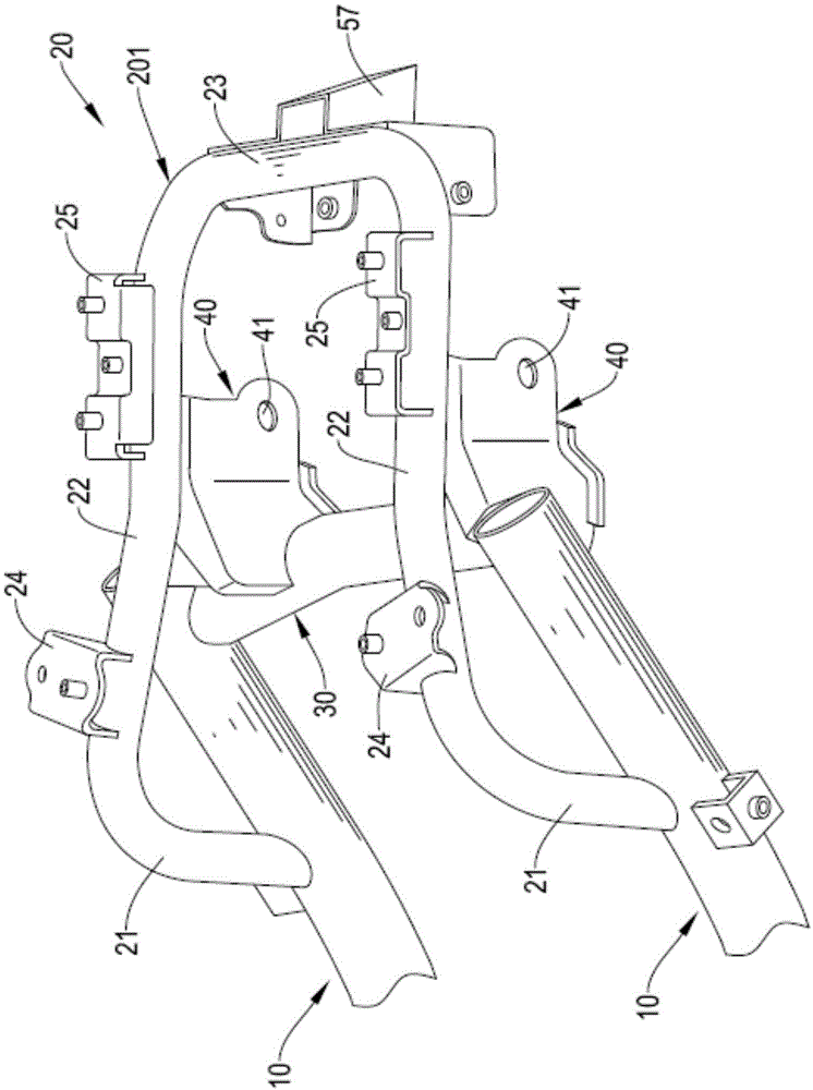
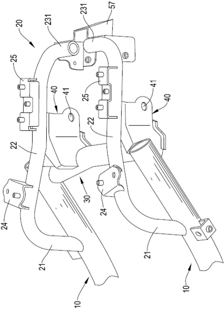
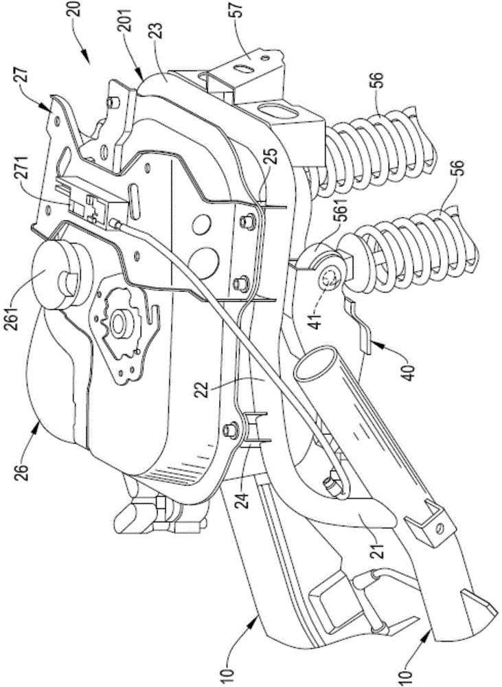
[0004] In view of the insufficient fixing strength of the expansion tube of the existing motorcycle rear frame, the limited space of the fuel tank and the interference of the position of the shock absorber bracket, the inventor improved its deficiencies and defects, and then created a rear frame assembly

Method used


Image

  • Rear frame assembly
  • Rear frame assembly
  • Rear frame assembly

Examples


Embodiment Construction

[0026] The technical means adopted by the present invention to achieve the intended purpose are further described below in conjunction with the accompanying drawings and preferred embodiments of the present invention.

[0027] see Figure 4 , the rear frame assembly of the present invention can be combined on the frame 50 of the motorcycle.

[0028] The vehicle frame 50 includes a head pipe 51 , a main pipe 52 , two side pipes 53 , a connecting section 54 , two pedal sections 55 , two shock absorbers 56 and a rear soil removal (fender) bracket 57 . One end of the main pipe 52 is fixed on the lower end of the head pipe 51 . Two side pipes 53 are respectively fixed on two sides of the other end of the main pipe 52 . Both ends of the connecting section 54 are respectively fixed on the two side pipes 53 . The two pedal sections 55 are respectively fixed on the two side tubes 53 .

[0029] see figure 1 and image 3 , The first embodiment of the rear frame assembly of the pre...


PUM


Abstract

The invention discloses a rear frame assembly. The rear frame assembly is provided with two auxiliary tubes and a rear tube assembly, wherein the two ends of the rear tube assembly are fixed on the two auxiliary tubes respectively; the rear tube assembly can be fixed on the auxiliary tubes without the need of tube expansion, and therefore can achieve a weight-reducing effect by virtue of small tubes, and the problem of end part breakage of the rear tube assembly is not liable to generate; and moreover, the strength of the rear tube assembly is reinforced, and a larger fuel tank can be installed.

Description

technical field [0001] The present invention relates to a motorcycle frame, especially to a rear frame assembly, which does not need to use expansion tubes to fix the rear frame, the strength of the rear frame assembly is enhanced, and a larger fuel tank can be installed. Moreover, it is easier for the user to lock the shock absorber and is less likely to be interfered. Background technique [0002] see Figure 5 as well as Figure 6 , the existing motorcycle tail frame is formed by combining the auxiliary pipe 70 and the tail pipe 80, the pipe diameter of the tail pipe 80 is smaller than the pipe diameter of the auxiliary pipe 70, and the two ends of the tail pipe 80 are combined by expanding the pipe on the secondary pipe 70 and fixed by welding all around, but expanding the two ends of the tail pipe 80 is likely to cause the end of the tail pipe 80 to break, so that the tail pipe The strength and load-bearing capacity of 80 are insufficient. [0003] A round hole 71 is...

Claims


Application Information

Patent Timeline
IPC IPC(8): B62K11/02B62K19/30
Inventor 柯世智
Owner KYMCO
Why Eureka
Eureka Blog
Learn More