It is used for the connection device between the active beam of the turnout and the stacking beam

A connecting device and active beam technology, which is applied in roads, tracks, buildings, etc., can solve problems such as insufficient strength or rigidity of the connecting device, decreased driving safety and stability, and weakened bearing capacity of the connecting device, so as to prevent left and right shaking, Improved stability and better pressure sharing

Active Publication Date: 2017-11-10
CHINA RAILWAY SIYUAN SURVEY & DESIGN GRP
View PDF7 Cites 0 Cited by
  • Summary
  • Abstract
  • Description
  • Claims
  • Application Information

AI Technical Summary

Problems solved by technology

[0005] However, the positioning connection device in this scheme also has obvious defects, that is, when the train passes through the connection device, the pressure acting on the movable end of the F rail completely acts on the guide wheel assembly and the extension end of the web of the switch beam. The unbalanced force will cause the vertical jump of the F rail; on the other hand, the lack of strength or stiffness of the connecting device in the vertical direction and instability will weaken the bearing capacity of the connecting device and reduce the bearing capacity of the entire track, which will lead to Decreased driving safety and stability

Method used


Image

  • It is used for the connection device between the active beam of the turnout and the stacking beam
  • It is used for the connection device between the active beam of the turnout and the stacking beam
  • It is used for the connection device between the active beam of the turnout and the stacking beam

Examples


Embodiment Construction

[0035] In order to make the object, technical solution and advantages of the present invention clearer, the present invention will be further described in detail below in conjunction with the accompanying drawings and embodiments. It should be understood that the specific embodiments described here are only used to explain the present invention, not to limit the present invention. In addition, the technical features involved in the various embodiments of the present invention described below can be combined with each other as long as they do not constitute a conflict with each other.

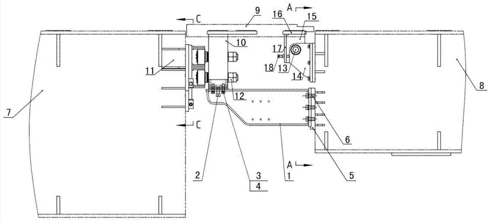
[0036] figure 1 It is a front structural diagram of a connecting device constructed according to an embodiment of the present invention. Such as figure 1 As shown, a connection device between the active beam of a medium-low speed maglev turnout and the stacking beam of this embodiment is arranged on the active beam of the turnout, which can move with the movement of the active beam of the turn...


PUM


Abstract

A connection apparatus used between an active beam (8) and a buttress beam (7) of a turnout, comprising: two moving F rails transversely symmetrically arranged along a track; a connecting crossbeam (10) fixedly arranged on the lower surfaces, close to the buttress beam (7) end, of the two moving F rails along the track line direction, used for connecting the two moving F rails; and an angle adjusting mechanism disposed at the other end, opposite to the connecting crossbeam (10), of the two moving F rails, used for properly adjusting a relative deflection angle of the moving F rails and the active beam (8) of the turnout; and further comprising a supporting beam (1) disposed at the bottom of the connecting crossbeam (10), one end of the supporting beam being fixed to a supporting beam base (5) which is mounted on the active beam (8) of the turnout, the other end of the supporting beam extending toward one side of the crossbeam (10), and the extending end being fixed to the bottom of the connecting crossbeam (10). The connection apparatus can improve the vertical stiffness of the connecting apparatus between the active beam (8) and the buttress beam (7), and improve the stability of the connecting apparatus of the turnout.

Description

technical field [0001] The invention belongs to the technical field of low- and medium-speed maglev track turnouts, and in particular relates to a connecting device used between active beams and stacking beams of a turnout. Background technique [0002] Turnout is a line connection device used in rail transit to transfer rolling stock from one track to another. It is usually laid in the throat area of ​​a station or at the intersection of two lines. The turnouts of medium and low speed maglev rail transit usually include turnout beams, stacking beams, trolleys, beam upper guide rails, driving devices, locking devices, movable end guide rails, and electrical control systems. When the train needs to change lanes, through the control of the electrical system, The locking device is unlocked, and the turnout beam moves from one track to the other under the action of the driving device. After the track at the movable end is flush with the track on the stacking beam, the locking de...

Claims


Application Information

Patent Timeline
Patent Type & Authority Patents(China)
IPC IPC(8): E01B25/34
CPCE01B25/00E01B25/34
Inventor 刘一平石建文盛勇郭志勇靖仕元秦超章致黄登郑洪
Owner CHINA RAILWAY SIYUAN SURVEY & DESIGN GRP
Why Eureka
Try Eureka