Frictionless, easy-to-open transfer valve

A transmission valve and switch technology, which is applied in the field of transmission valves, can solve problems such as inability to seal synchronously, incomplete fit, difficulty in lifting, etc., and achieve the effects of prolonging service life, no friction, and good sealing effect

Active Publication Date: 2017-09-19
SHENZHEN XINYUREN TECH
View PDF1 Cites 0 Cited by
  • Summary
  • Abstract
  • Description
  • Claims
  • Application Information

AI Technical Summary

Problems solved by technology

The traditional vacuum drying is carried out in a separate vacuum oven. The rolled battery pole pieces are placed in a separate vacuum oven, and then the vacuum oven is heated, vacuumed and cooled to a certain temperature. Finally, the battery pole piece is taken out; because the traditional vacuum oven has low baking efficiency and other problems, in order to improve efficiency, someone has developed a tunnel-type vacuum oven, and the adjacent box of the tunnel-type vacuum oven The sealing problem between them is very important, it affects the drying effect and efficiency of the battery pole piece, therefore, in order to improve the sealing between the adjacent boxes of the tunnel vacuum oven, people also pay attention to the sealing of the tunnel vacuum oven. For further research and improvement, for example, Chinese patent document CN 204163565 U discloses a self-sealed door, which includes a first door panel and a second door panel arranged in parallel, and a The lifting mechanism for lifting the first door panel and the second door panel is provided with at least two hinges between the first door panel and the lifting mechanism, one end of the hinge is hinged with the first door panel, and the other is hinged. One end is hinged with the lifting mechanism, and at least two hinges are arranged between the second door panel and the lifting mechanism, one end of the hinge is hinged with the second door panel, and the other end is hinged with the lifting mechanism. The mechanism is hinged, a first roller is provided at the lower end of the first door panel, a first slope with a low left and a high right is provided under the first roller, and a second roller is provided at the lower end of the second door panel, A second slope with a high left and a low right is provided below the second roller
[0003] In the above-mentioned self-sealed door in the prior art, a first roller and a second roller are respectively provided at the lower ends of the first door panel and the second door panel, and a first inclined plane and a first slope are respectively provided under the first roller and the second roller. The second inclined plane, however, causes the first door panel and the second door panel to be sealed in this way, and the planes of the first door panel and the second door panel cannot be sealed synchronously due to uneven force, that is, the first door panel or the second door panel will not be sealed synchronously. The bottom of the second door panel has been fitted to the oven, but the upper part has not yet been fully fitted; secondly, the self-sealed door in the prior art, due to the gap between the first roller and the first slope, and between the second roller and the second slope There is friction between them, so it is more laborious to open or close, and it takes a certain amount of time to seal well. Moreover, when the first door panel and the second door panel are sealed, due to the influence of manufacturing accuracy or installation accuracy, it will cause the first The door panel and the second door panel are not sealed synchronously, that is, the first door panel is sealed well, but the second door panel is not yet sealed. In this way, it will take a long time to debug to meet the usable requirements, and it will also cause sealing effect Not good; in addition, the existing lifting device uses a rack and pinion structure, because the rack is too long and deformed, resulting in difficulty in lifting

Method used


Image

  • Frictionless, easy-to-open transfer valve
  • Frictionless, easy-to-open transfer valve
  • Frictionless, easy-to-open transfer valve

Examples


Embodiment Construction

[0024] In the description of the present invention, it should be understood that the orientation or positional relationship indicated by the terms "center", "upper", "lower", "front", "rear", "left", "right" etc. are based on The orientation or positional relationship shown in the drawings is only for the convenience of describing the present invention and simplifying the description, and does not indicate or imply that the referred device or element must have a specific orientation, be constructed and operated in a specific orientation, and therefore cannot be understood as Limitations on the Invention. In addition, the terms "first" and "second" are used for descriptive purposes only, and should not be understood as indicating or implying relative importance.

[0025] In the description of the present invention, it should be noted that unless otherwise specified and limited, the terms "installation", "connection" and "connection" should be understood in a broad sense, for ex...


PUM


Abstract

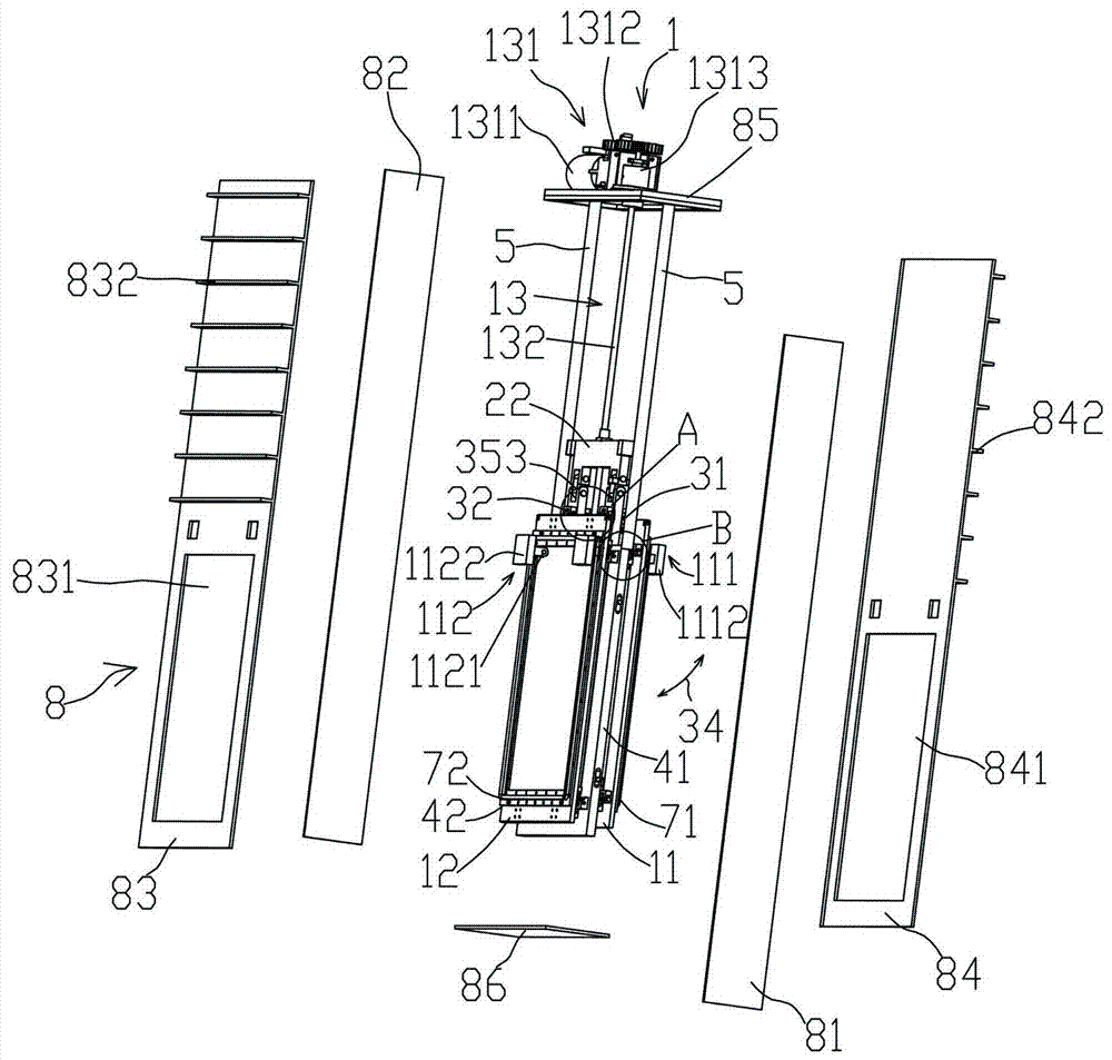
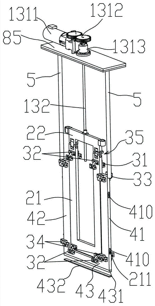
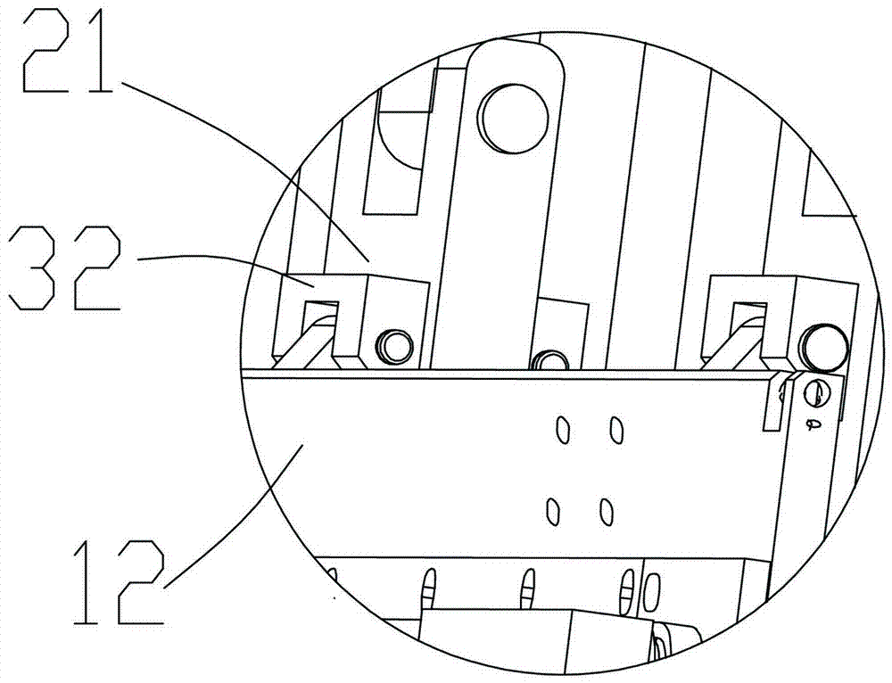
A friction-free conveying valve easy to open and close comprises a conveying valve element. The conveying valve element comprises a first sealing door, a second sealing door, a lifting mechanism and a first lifting plate. The first sealing door and the second sealing door are connected with the first lifting plate through first hinge pieces and second hinge pieces respectively. A first limiting piece and a second limiting piece are arranged on the two sides of the first lifting plate in the vertical direction respectively. The first sealing door is connected with the first limiting piece and the second limiting piece through third hinge pieces. The second sealing door is connected with the first limiting piece and the second limiting piece through fourth hinge pieces. The first hinge pieces and the second hinge pieces are arranged to be of a top-down structure from the first lifting plate to the first sealing door or the second sealing door. The third hinge pieces and the fourth hinge pieces are arranged to be of a down-top structure from the first limiting piece and the second limiting piece to the first sealing door or the second sealing door. The friction-free conveying valve easy to open and close has the advantages of being free of friction, more convenient to open or close and better in sealing effect.

Description

technical field [0001] The invention relates to a transmission valve, in particular to a frictionless and easy-to-open transmission valve suitable for a vacuum tunnel oven. Background technique [0002] At present, in the process of making new energy materials, it is necessary to bake new energy materials to remove water if necessary. For example, in the production process of lithium batteries, it needs to be vacuum dried to reduce lithium The moisture contained in the battery, so that it meets the corresponding use requirements. The traditional vacuum drying is carried out in a separate vacuum oven. The rolled battery pole pieces are placed in a separate vacuum oven, and then the vacuum oven is heated, vacuumed and cooled to a certain temperature. Finally, the battery pole piece is taken out; because the traditional vacuum oven has low baking efficiency and other problems, in order to improve efficiency, someone has developed a tunnel-type vacuum oven, and the adjacent box...

Claims


Application Information

Patent Timeline
Patent Type & Authority Patents(China)
IPC IPC(8): F16K3/02F16K3/316F16K3/30F16K31/44
CPCF16K3/0227F16K3/0254F16K3/029F16K3/3165
Inventor 杨志明
Owner SHENZHEN XINYUREN TECH
Why Eureka
Try Eureka