an incinerator

A technology for incinerators and furnace bodies, applied in the field of incinerators, can solve problems such as insufficient working life, uneven incineration of incinerators, etc., and achieve the effect of increasing service life, improving efficiency, and uniform incineration

Active Publication Date: 2018-06-29
江苏碧诺环保科技有限公司
View PDF6 Cites 0 Cited by
  • Summary
  • Abstract
  • Description
  • Claims
  • Application Information

AI Technical Summary

Problems solved by technology

[0004] Therefore, the technical problem to be solved by the present invention is to overcome the problems of uneven and insufficient incineration and low working life of incinerators in the prior art, thereby providing an incinerator with uniform and sufficient incineration and high working life

Method used


Image

  • an incinerator
  • an incinerator
  • an incinerator

Examples


Embodiment 1

[0037] This embodiment provides an incinerator, such as figure 1 and 2 shown, including,

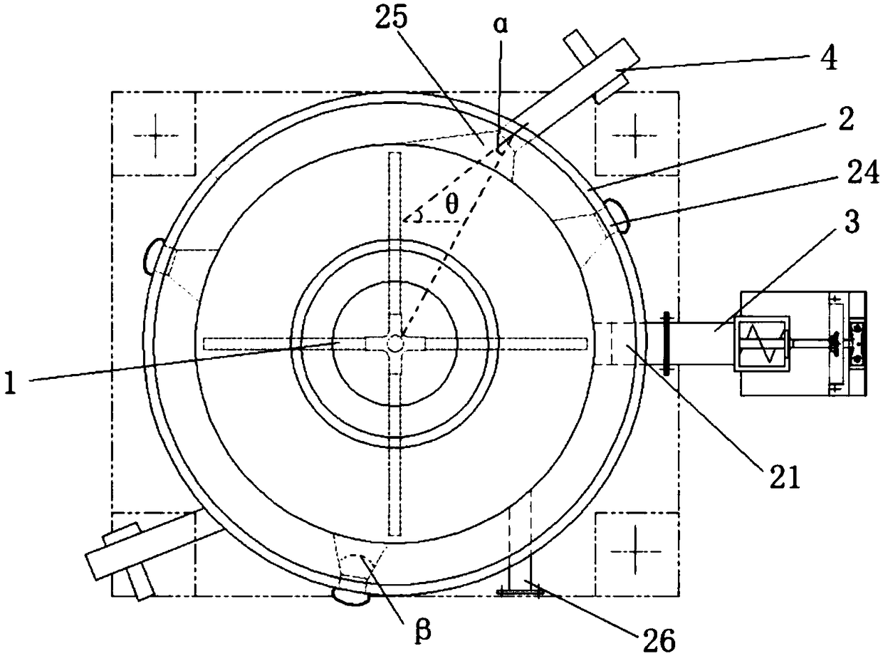
[0038] furnace body 2, such as figure 1 The bottom shown is cylindrical, the upper part is truncated circular, the side wall is provided with a feed inlet 21 and a high-temperature gas outlet 25, the top is provided with an air outlet 23, and the bottom is provided with a discharge outlet 22;

[0039] The burner 4 communicates with the high-temperature gas tuyeres 25 and is used for blowing high-temperature gas into the interior of the furnace body 2;

[0040] Stirring device for stirring the materials in the furnace body 2;

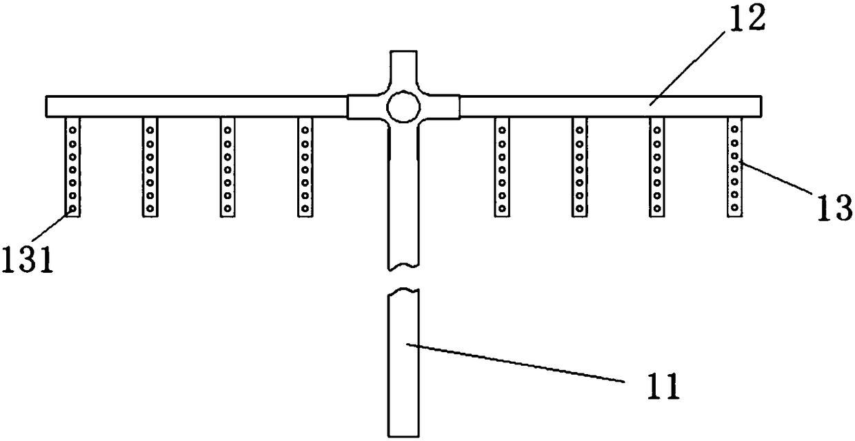
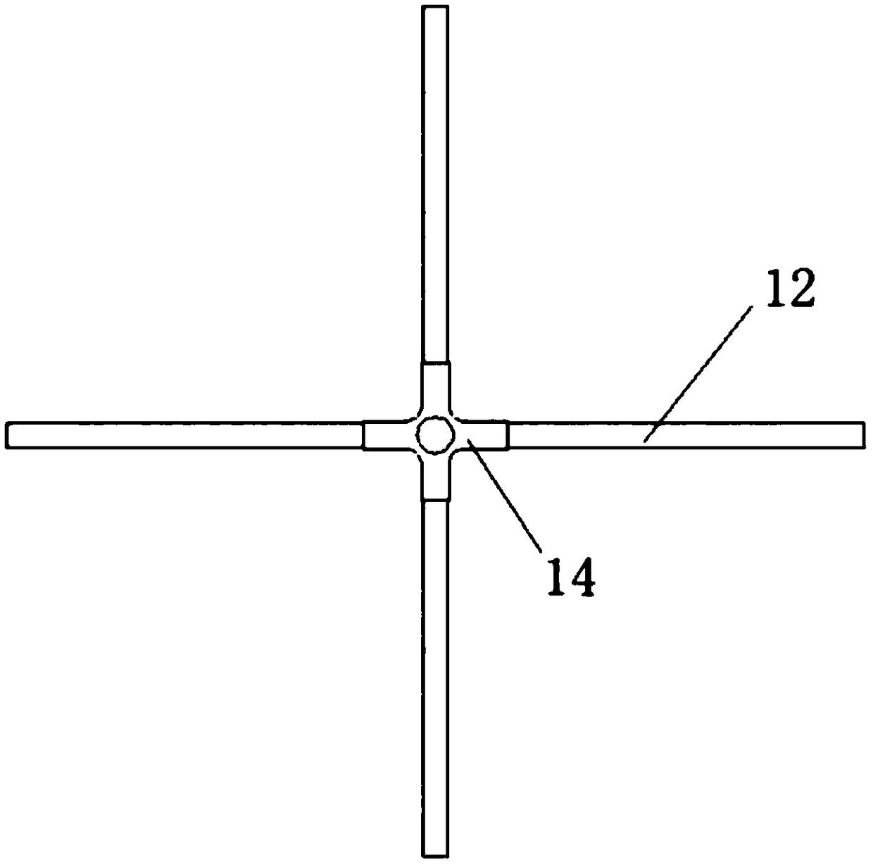
[0041] The stirring device includes a rotating shaft 11, which extends vertically from the outside of the furnace body 2 through the bottom wall of the furnace body 2 into the inside of the furnace body 2, and is hollow inside, driven by a power device to be able to rotate;

[0042] The horizontal tube 12 is arranged on the rotating shaft 11, arranged horizont...


PUM


Abstract

The invention provides an incinerator. A rotating shaft in a stirring device, a transverse pipe and vertical pipes are arranged inside an incinerator body; a power device and a fan are arranged outside the incinerator body; during incineration of the incinerator body, the power device drives the rotating shaft to rotate, meanwhile, the transverse pipe and the vertical pipes move along with rotation of the rotating shaft, and accordingly the effect of stirring materials in the incinerator body mechanically is achieved. Meanwhile, the fan is used for pumping gas into the incinerator body from the outside of the incinerator body via the rotating shaft, the transverse pipe and the vertical pipes in sequence, and the gas is sprayed out from through holes; on the one hand, the flowing gas further stirs the materials in the incinerator body, the stirring range is extended, no stirring dead corner exists in the incinerator body, and incineration is more uniform and sufficient; on the other hand, the temperature of the rotating shaft, the transverse pipe and the vertical pipes can be reduced through the flowing gas and is prevented from being too high in the high-temperature incinerator body, strength reduction and deformation caused when the temperature of the rotating shaft, the transverse pipe and the vertical pipes is too high are avoided, and the service life of the incinerator is prolonged.

Description

technical field [0001] The invention relates to the technical field of pollutant treatment equipment, in particular to an incinerator. Background technique [0002] The incinerator is a harmless treatment equipment commonly used in the harmless treatment of medical and domestic waste, sludge and animals. Its principle is to use coal, fuel oil, gas and other fuels to incinerate the objects to be processed at high temperature, so as to achieve the purpose of reduction and harmlessness. In order to improve the effect of incineration, a stirring device is usually installed in the incinerator to stir the materials in the incinerator so that the materials can be fully incinerated. [0003] For example, Chinese patent document CN2733186Y discloses a kind of incinerator, which is composed of a transmission shaft and a stirring rod. When the transmission shaft is rotating, the material in the incinerator is stirred by the stirring rod. There is a certain dead angle, that is, the ar...

Claims


Application Information

Patent Timeline
Patent Type & Authority Patents(China)
IPC IPC(8): F23G5/08F23G5/44
CPCF23G5/08F23G5/44
Inventor 蒋子厚蒋子才赵钱亮
Owner 江苏碧诺环保科技有限公司
Why Eureka
Try Eureka