Vacuum lignite drying device and using method thereof

A technology of drying device and vacuum dryer, which is applied in the direction of drying solid materials, drying solid materials without heating, drying, etc., which can solve the problems of complex system, high risk, and large discharge volume, and achieve reasonable equipment structure and high efficiency. Safety, effect of large heat transfer temperature difference

Active Publication Date: 2016-03-09
CHANGZHENG ENG
View PDF7 Cites 2 Cited by
  • Summary
  • Abstract
  • Description
  • Claims
  • Application Information

AI Technical Summary

Problems solved by technology

[0005] The purpose of the present invention is to provide a vacuum lignite drying device and its use method to solve the problems of high energy consumption, large discharge, high risk and complicated system in the drying method in the prior art, and to realize the beneficial The zero precipitation of volatile matter improves the safety of the system and realizes the sustainable utilization of resources

Method used


Image

  • Vacuum lignite drying device and using method thereof

Examples


Embodiment 1

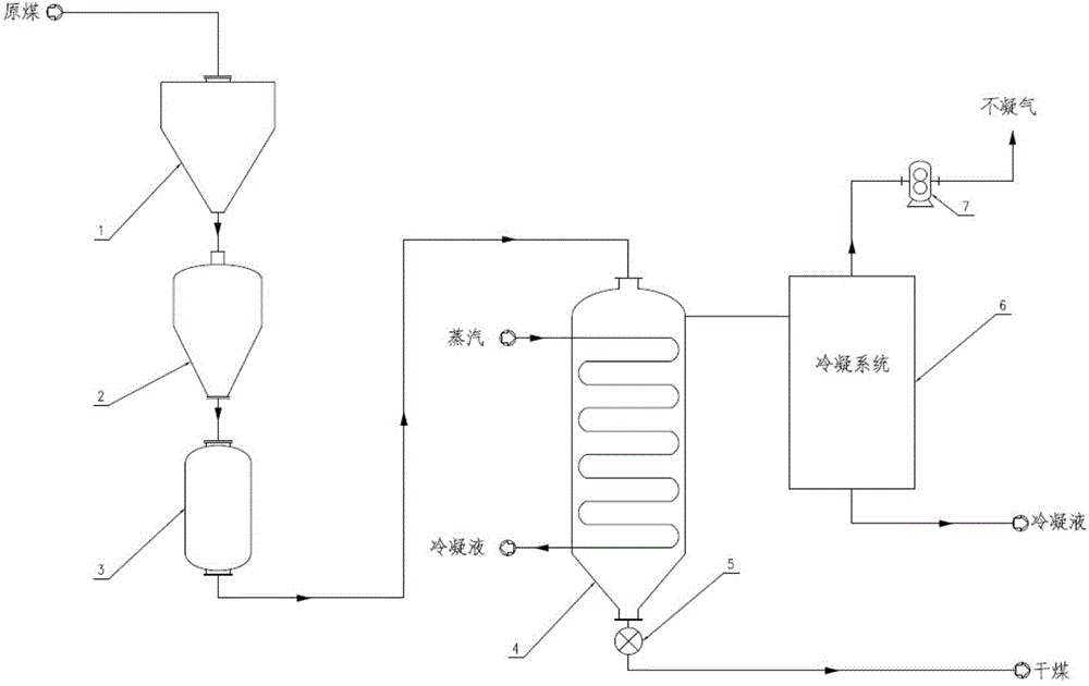
[0023] A vacuum lignite drying device, including a raw coal bunker 1, characterized in that it also includes a vacuum lock hopper 2 connected in sequence, a vacuum feeding tank 3, a vacuum dryer 4 and a condensation system 6, and above the condensation system 6 is a Vacuum pump7.

Embodiment 2

[0025] A vacuum lignite drying device, similar to Example 1, the difference is that a dry coal outlet is provided below the vacuum dryer 4 through a discharge valve 5; The vacuum feed tank 3 is set under the vacuum lock hopper 2 through a valve; the top of the raw coal bunker 1 is provided with a raw coal inlet; the upper part of the vacuum dryer 4 is provided with a steam inlet, and the lower part is provided with a condensation liquid outlet; the top of the condensation system 6 is provided with a non-condensable gas outlet connected to the vacuum pump 7, and the bottom is provided with a condensate outlet.

Embodiment 3

[0027] A method of using a vacuum lignite drying device. First, the lignite is stored in the raw coal bunker 1 and sent to the vacuum lock hopper 2 through a valve. At this time, the valve at the bottom of the vacuum lock hopper 2 is in a closed state, and its upper part is communicated with the raw coal bunker 1. , in a state of normal pressure; after the discharge is completed, the valve on the top of the vacuum lock hopper 2 is closed, and a vacuum environment is established. After the vacuum degree reaches the set value, the discharge valve 5 at the lower part of it is opened, and the material is discharged to the vacuum feed tank 3; At this time, the vacuum feeding tank 3 continues to send the raw material lignite into the vacuum drier 4, and the lignite exchanges heat with the atmospheric pressure steam that is passed into the heat exchange tube inside the vacuum drier 4, because the inside of the vacuum drier 4 is in a negative pressure environment, the boiling point of ...


PUM


Abstract

The invention relates to a vacuum lignite drying device and a using method thereof. The device comprises a raw coal bunker, and further comprises a vacuum lock hopper, a vacuum feeding tank, a vacuum drying machine and a condensation system, the vacuum lock hopper, the vacuum feeding tank, the vacuum drying machine and the condensation system are sequentially connected, and a vacuum pump is arranged above the condensation system; the problems that in the prior art, a drying method is high in energy consumption, large in discharging amount, high in dangerousness, complex in system and the like are solved; and zero precipitation of beneficial volatile matter in coal is achieved, the system safety is improved, and the continuous utilization of resources is achieved.

Description

technical field [0001] The invention belongs to the technical field of vacuum drying, and relates to a vacuum drying device, in particular to a vacuum drying device suitable for low-rank coal such as lignite and a method for using the same. Background technique [0002] Lignite is the coal with the lowest degree of coalification and is named for its brown or dark brown appearance. The geological reserves of lignite in the world are about 4 trillion tons, accounting for 40% of the global coal reserves. my country is rich in lignite resources. According to statistics at the end of the 20th century, the country has proven reserves of lignite of 130 billion tons, accounting for about 13% of the country's total coal reserves. Among the proven lignite reserves in China, the northeastern region of Inner Mongolia is the largest, accounting for about 3 / 4 of the national lignite reserves; the southwest region, dominated by Yunnan Province, accounts for about 1 / 5 of the country's lign...

Claims


Application Information

Patent Timeline
Patent Type & Authority Applications(China)
IPC IPC(8): F26B5/04F26B25/00
Inventor 马超章刚王璠
Owner CHANGZHENG ENG
Why Eureka
Try Eureka