Combined converting terminal and automotive relay

A technology of automotive relays and terminals, applied in circuits, electrical components, coupling devices, etc., can solve the problems of inconvenient plugging and unplugging, high terminal space occupation rate, and affecting electrical performance, so as to reduce space occupation rate and save assembly process , The effect of easy plugging and unplugging operation

Active Publication Date: 2016-03-09
XIAMEN HONGFA AUTOMOTIVE ELECTRONICS
View PDF8 Cites 2 Cited by
  • Summary
  • Abstract
  • Description
  • Claims
  • Application Information

AI Technical Summary

Problems solved by technology

Since the multiple terminals are usually fixed on the main body of the component by means of clamping or plugging, and often need to be bent, it has the following disadvantages: each terminal is not strong enough, and it is easy to loosen after repeated p

Method used


Image

  • Combined converting terminal and automotive relay
  • Combined converting terminal and automotive relay
  • Combined converting terminal and automotive relay

Examples


Embodiment 1

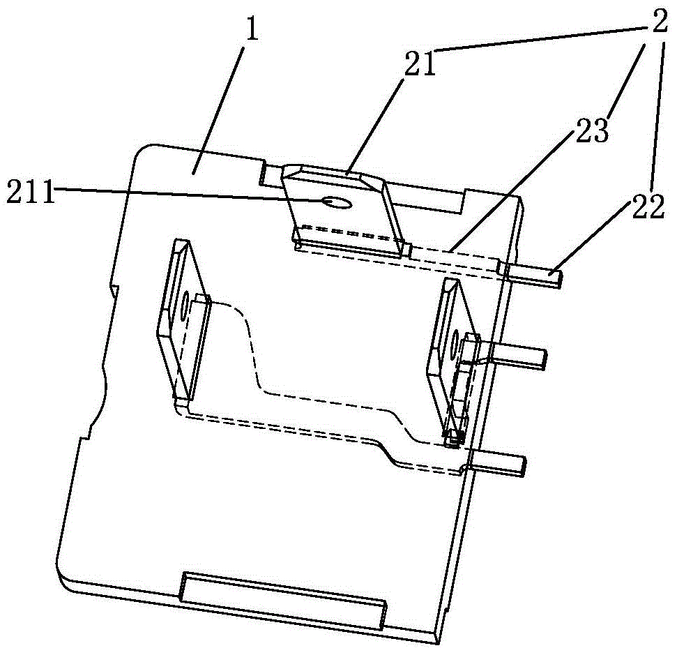
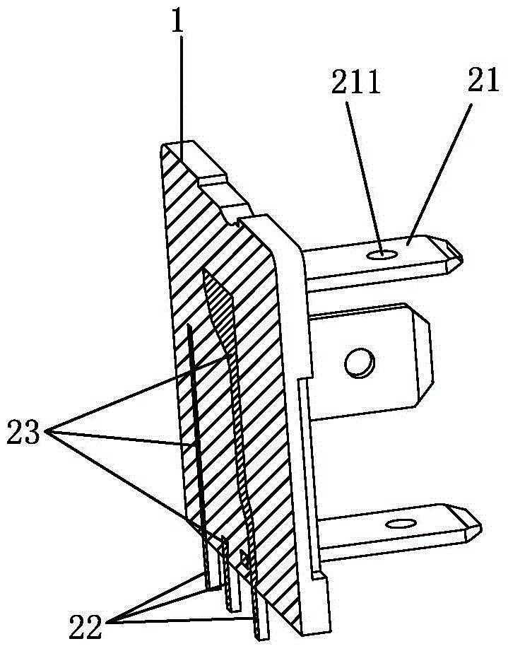
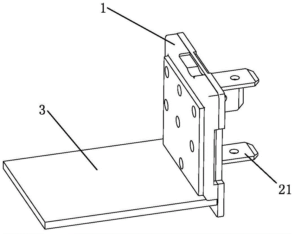
[0029] See figure 1 , figure 2 As shown, a combined conversion terminal of the present invention includes a plate-shaped insulating body 1 and three connecting terminals 2. The three connecting terminals 2 are respectively insert-molded in the insulating body 1 when the insulating body 1 is injected, and each The connecting terminals 2 are electrically insulated from each other; each connecting terminal 2 includes a first terminal 21, a second terminal 22 and a third terminal 23 respectively, and the first terminal 21 and the second terminal 22 extend from two adjacent surfaces of the insulating body 1, And the first terminal 21 is electrically connected to the second terminal 22 through the third terminal 23 .

[0030] In this embodiment, the first terminals 21 of the three connecting terminals 2 extend from the same surface of the insulating body 1, and the second terminals 22 of the three connecting terminals 2 extend from the same surface of the insulating body 1. exten...

Embodiment 2

[0045] See Figure 5-Figure 8 As shown, a combined conversion terminal of the present invention has nine connection terminals 2, and the first terminals 21 of the nine connection terminals 2 are located on the same surface of the insulating body 1, and the second terminals 22 of the nine connection terminals 2 are also Located on the same surface of the insulating body 1 and on two adjacent surfaces of the insulating body 1 with the first terminal 21 , the third terminals 23 of the nine connecting terminals 2 are all embedded in the insulating body 1 .

[0046] Due to the miniaturization requirements of automotive relays, the size of the insulating body 1 is limited. Therefore, the first terminals 21 of some connecting terminals 2 overlap in the direction perpendicular to the PCB assembly. In order to ensure that the connecting terminals 2 are electrically insulated from each other and the second terminals 22 are along the Arranged in a "" shape, the third terminals 23 in this...


PUM


Abstract

The invention discloses a combined converting terminal and an automotive relay. The combined converting terminal includes a plate-shaped insulating body, and at least two connecting terminals; wherein the at least two connecting terminals are embedded and molded in the insulating body during injection molding of the insulating body respectively, and the connecting terminals are in electrical insulation with each other; and each connecting terminal includes a first terminal, a second terminal and a third terminal, the first terminal and the second terminal extend out from adjacent two surfaces of the insulating body, and the first terminal is electrically connected to the second terminal through the third terminal. The automotive relay includes a PCB assembly and the combined converting terminal; the second terminals of the at least two connecting terminals are pins respectively and are inserted into at least two pin inserting holes arranged in the PCB assembly respectively; and the distance between the second terminals of the at least two connecting terminals fits the distance between the at least two pin inserting holes of the PCB assembly. According to the invention, the connections between various connecting terminals and the insulating body are more solid and are not easy to loosen and fall off.

Description

technical field [0001] The invention relates to the field of automobile relays, in particular to a combined switching terminal and an automobile relay. Background technique [0002] At present, there are mainly three types of automotive relays in the prior art: capacitive type, wing type, and electronic type. The core component inside the automotive relay is a PCB component welded with MCU, MOS tube, capacitor, resistor and other components. The PCB component is electrically connected to the outside world through a terminal connection component. The terminal component mainly includes a component body and a plurality of terminals mounted on the component body. Since the multiple terminals are usually fixed on the main body of the component by means of clamping or plugging, and often need to be bent, it has the following disadvantages: each terminal is not strong enough, and it is easy to loosen after repeated plugging and unplugging. Even fall off, thereby affecting the ele...

Claims


Application Information

Patent Timeline
IPC IPC(8): H01R13/405
Inventor 李进廷朱华雄陈可璜
Owner XIAMEN HONGFA AUTOMOTIVE ELECTRONICS
Why Eureka
Try Eureka