Laser receiving structure, combat equipment shell and combat equipment

A technology of laser receiving and equipment, applied in the field of optical structure, can solve the problems of narrow laser beam and control chip pin occupation, etc., to achieve the effect of reducing pins, reducing the number, and improving the projection range

Active Publication Date: 2017-05-10
TENCENT TECH (SHENZHEN) CO LTD
View PDF5 Cites 0 Cited by
  • Summary
  • Abstract
  • Description
  • Claims
  • Application Information

AI Technical Summary

Problems solved by technology

[0004] In the process of realizing the present invention, the inventor found that the prior art has at least the following problems: due to the narrow laser beam, in order to improve the success rate of laser reception, it is often necessary to install a large number of laser receiving components on the device, resulting in the control chip of the device A large number of pins are occupied by laser receiving components

Method used


Image

  • Laser receiving structure, combat equipment shell and combat equipment
  • Laser receiving structure, combat equipment shell and combat equipment
  • Laser receiving structure, combat equipment shell and combat equipment

Examples


Embodiment Construction

[0038] In order to make the object, technical solution and advantages of the present invention clearer, the implementation manner of the present invention will be further described in detail below in conjunction with the accompanying drawings.

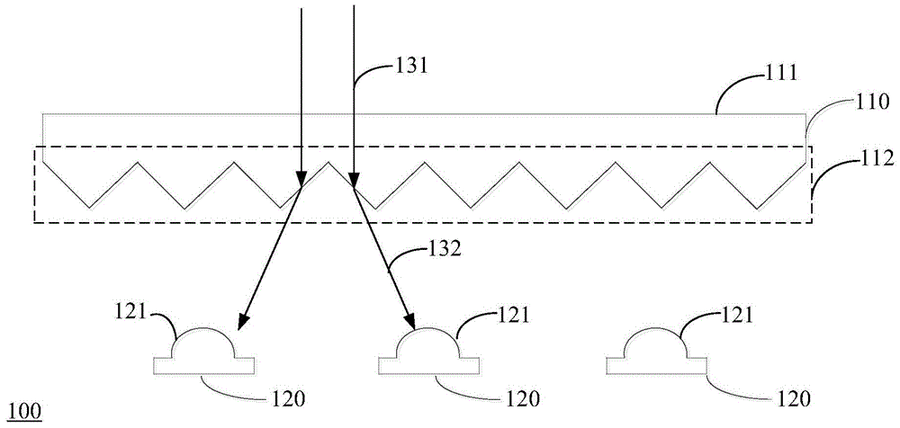
[0039] Figure 1A A schematic structural diagram of a laser receiving structure provided by an embodiment of the present invention is shown. The laser receiving structure includes a light scattering component 110 and at least one laser receiving component 120 .

[0040] The light scattering component 110 includes a light entrance surface 111 and a light exit surface 112 , and the light diffusion component 110 is a component for scattering the laser light incident on the light entrance surface 111 and then emitting from the light exit surface 112 .

[0041] As shown in Figure 1, the upper surface of the light-scattering component 110 is a light-incoming surface 111, which is used to receive the laser light 131 emitted by an external las...


PUM


Abstract

A laser receiving structure, a battle device housing, and a battle device, belonging to the field of optical structures. The laser receiving structure comprises a laser scattering component (110) and at least one laser receiving assembly (120). The laser scattering component (110) comprises a light incident surface (111) and a light emergent surface (112), and the laser scattering component (110) is used for scattering a laser (131) that enters the light incident surface (111) and transmitting the scattered laser out of the light emergent surface (112). The light incident surface (111) is opposite to the incident direction of the laser (131), and a receiving end (121) of the at least one laser receiving assembly (120) is opposite to the light emergent surface (112). The light emergent surface (112) comprises protrusion structures arranged as an array. Alternatively, the light emergent surface (112) is a smooth surface and the laser scattering component (110) is made by using a material having the laser scattering characteristics. Therefore, the quantity of laser receiving assemblies in a device is reduced, so that the overall energy consumption of the device is reduced.

Description

technical field [0001] The invention relates to the field of optical structures, in particular to a laser receiving structure, a battle equipment shell and a battle equipment. Background technique [0002] Laser modulation carrier emission technology is a technology that utilizes the good directivity and low divergence angle characteristics of laser for data transmission. [0003] Laser modulation carrier emission technology is widely used in the field of equipment control. For example, when device A uses laser to transmit data to device B, device A modulates the laser light according to the data to be transmitted, and emits it through the laser emitting device. After receiving the laser light, the laser receiving component on device B demodulates the laser light to obtain the data carried in the laser light. [0004] In the process of realizing the present invention, the inventor found that the prior art has at least the following problems: due to the narrow laser beam, i...

Claims


Application Information

Patent Timeline
Patent Type & Authority Patents(China)
IPC IPC(8): H04B10/67
CPCG02B6/42H04B10/67
Inventor 杨勇鲁四喜赵明荆彦青
Owner TENCENT TECH (SHENZHEN) CO LTD
Why Eureka
Try Eureka