Large-shaft-shoulder stirring head suitable for high-speed friction-stir welding, and welding method

A technology of friction welding and high-speed stirring, which is applied in welding equipment, non-electric welding equipment, metal processing equipment, etc., can solve the problems that it is difficult to realize high-speed friction stir welding of medium and thick plates, and achieve improved welding efficiency, good weld shape, and reduced The effect of the probability of forming defects

Inactive Publication Date: 2016-03-16
HARBIN INST OF TECH
View PDF8 Cites 6 Cited by
  • Summary
  • Abstract
  • Description
  • Claims
  • Application Information

AI Technical Summary

Problems solved by technology

[0005] The purpose of the present invention is to solve the problem that the current conventional shoulders are difficult to achieve high-speed friction stir welding of medium and thick plates, and then propose a large shoulder (diameter is more than 5 times the thickness of the plate) stirring head suitable for high-speed friction stir welding and Welding method

Method used


Image

  • Large-shaft-shoulder stirring head suitable for high-speed friction-stir welding, and welding method
  • Large-shaft-shoulder stirring head suitable for high-speed friction-stir welding, and welding method
  • Large-shaft-shoulder stirring head suitable for high-speed friction-stir welding, and welding method

Examples


specific Embodiment approach 1

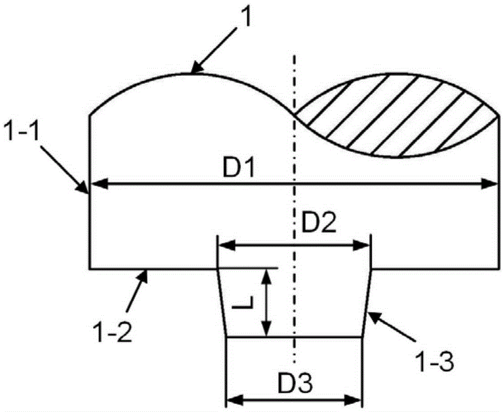
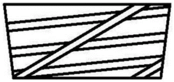
[0029] Specific implementation mode one: combine Figure 1 to Figure 5 Describe this embodiment, a large shoulder stirring head suitable for high-speed friction stir welding described in this embodiment, the large shoulder stirring head includes a clamping area 1-1, a shoulder 1-2 and a stirring needle 1-3 , the center of the clamping area 1-1, the center of the shaft shoulder 1-2 and the center of the stirring needle 1-3 are set coaxially; the shaft shoulder 1-2 is a large shaft shoulder with a diameter D1 greater than 5 times the thickness of the workpiece to be welded, and the shaft shoulder 1 The variable-groove deep Archimedean spiral groove that is different from the conventional equal-groove deep Archimedean spiral groove is processed on the -2 plane. The curve equation of the variable-groove deep Archimedean spiral groove is ρ=a+bθ, and ρ is Polar diameter, θ is the polar angle, indicating the total degree of the Archimedes spiral, a is the polar diameter when θ = 0, b...

specific Embodiment approach 2

[0030] Specific implementation mode two: combination figure 1 Illustrate the present embodiment, the curve equation of the processed Archimedes spiral groove on the shaft shoulder 1-2 plane in the present embodiment is: The depth at the beginning of the spiral groove is 0.5mm, and the depth at the end of the spiral groove is 1.0mm; the lead of the first set of taper threads on the side of the stirring needle 1-3 is 2mm, and the lead of the second set of taper threads is 12mm. Other compositions and connections are the same as in the first embodiment.

[0031] The technical effect of this embodiment is: the large shoulder stirring head can ensure sufficient heat input to form sufficient plastic metal in the high-speed friction stir welding process; the existence of the Archimedes spiral groove when the stirring head rotates counterclockwise The metal is guided from the end of the spiral groove along the spiral groove to the beginning of the spiral groove, and as the flow dist...

specific Embodiment approach 3

[0032] Specific implementation mode three: combination Figure 4 to Figure 5 Describe this embodiment, a kind of high-speed friction stir welding method described in this embodiment is characterized in that it comprises the following steps:

[0033] Step 1. Determination of the dimensions of the large shoulder stirring head:

[0034] Determine the diameter D1 of the shoulder 1-2, the root diameter D2 of the stirring needle 1-3, and the end diameter of the stirring needle 1-3 according to the thickness h of the first welded workpiece 2-1 and the second welded workpiece 2-2 D3 and the length L of the stirring needle 1-3; wherein the diameter D1 of the shoulder 1-2 is 5-10 times the thickness h of the first welded workpiece 2-1 and the second welded workpiece 2-2, and the stirring needle 1- The root diameter D2 of 3 is 2-4 times the thickness h of the first welded workpiece 2-1 and the second welded workpiece 2-2, and the end diameter D3 of the stirring pin 1-3 is the first welded...


PUM


Abstract

The invention discloses a large-shaft-shoulder stirring head suitable for high-speed friction-stir welding, and a welding method, and relates to a large-shaft-shoulder stirring head and a welding method. The invention aims at solving the problem that the present conventional shaft-shoulder stirring head is difficult to realize high-speed friction-stir welding for a medium-thickness plate. The stirring head is composed of three parts, that is, a clamping area, a shaft shoulder and a stirring needle, wherein the centre of the clamping area, the circle centre of the shaft shoulder and the centre of the stirring needle are coaxially arranged; and a large shaft shoulder with a diameter which is 5 times greater than a plate thickness is used as the shaft shoulder, an Archimedes spiral groove with a variable groove depth is machined in the plane of the shaft shoulder, a conical stirring needle is used as the stirring needle, and two conical threads with different leads are machined on the side surface. The method comprises the following steps: step 1, determination for each dimension of the large-shaft-shoulder stirring head; step 2, clamping for welded workpieces; step 3, location for the stirring head; step 4, determination for penetrating parameters; and step 5, determination for advancing parameters. The stirring head and the welding method, which are disclosed by the invention, are suitable for high-speed friction-stir welding (with a speed of not less than 1500mm/min) for an aluminium alloy medium-thickness plate (with a thickness of not less than 3mm).

Description

technical field [0001] The invention relates to a large shoulder stirring head and a welding method, in particular to a large shoulder stirring head suitable for high-speed friction stir welding and a welding method. Background technique [0002] In 1991, the British Welding Institute invented a new type of solid phase joining technology - friction stir welding, which effectively avoids welding defects such as cracks and pores during the solidification of the molten pool in the traditional fusion welding method, and it is easy to obtain defect-free welding. High-quality joints have been developed rapidly and widely used, especially suitable for welding low melting point light metal materials such as aluminum alloys. [0003] During the friction stir welding process, the heat generated by the friction between the shaft shoulder and the workpiece accounts for 80-90% of the total heat generated. However, there is no mature theory for the size design of the stirring head, and mo...

Claims


Application Information

Patent Timeline
Patent Type & Authority Applications(China)
IPC IPC(8): B23K20/12B23K20/26
CPCB23K20/12B23K20/26
Inventor 刘会杰刘向前胡琰莹李继超王欢林喆曾凡勇
Owner HARBIN INST OF TECH
Why Eureka
Try Eureka