Container welding positioning system

A welding positioning and container technology, which is applied to household containers, welding equipment, auxiliary welding equipment, etc., can solve the problems of finished products that cannot be taken out, easy to break, and production delays, and achieve high-efficiency welding quality, reduce production costs, and accurate positioning. Effect

Active Publication Date: 2017-04-12
LINGHANG IND & TRADE ZHEJIANG
View PDF8 Cites 2 Cited by
  • Summary
  • Abstract
  • Description
  • Claims
  • Application Information

AI Technical Summary

Problems solved by technology

During welding, the welding torch will arc and generate heat, so it is easy to burn out the positioning ring of the bottle body and the positioning seat of the bottom of the bottle, causing production delays
In addition, there will be ribs at the welding position after welding, and because the bottle body and the bottle body positioning ring have a zero tolerance fit, the finished product cannot be taken out, and it is stuck between the bottle body positioning ring and the bottle bottom positioning seat
In order to solve this problem, the existing technology will make the outer diameter of the bottom of the bottle smaller, about 0.1mm smaller than the diameter of the bottle body, so that although the finished product after welding can be taken out smoothly, the welded cross section will be too small, which will affect the mechanical properties of the product , easy to break

Method used


Image

  • Container welding positioning system
  • Container welding positioning system
  • Container welding positioning system

Examples


Embodiment Construction

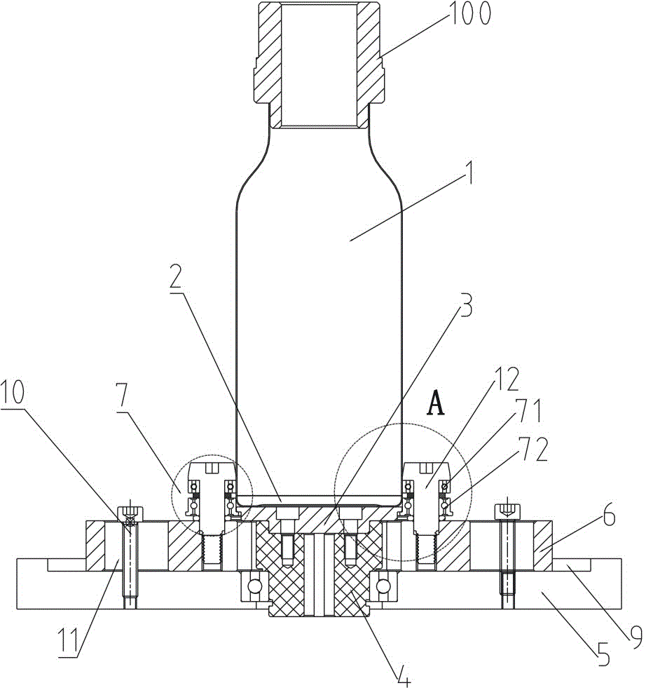
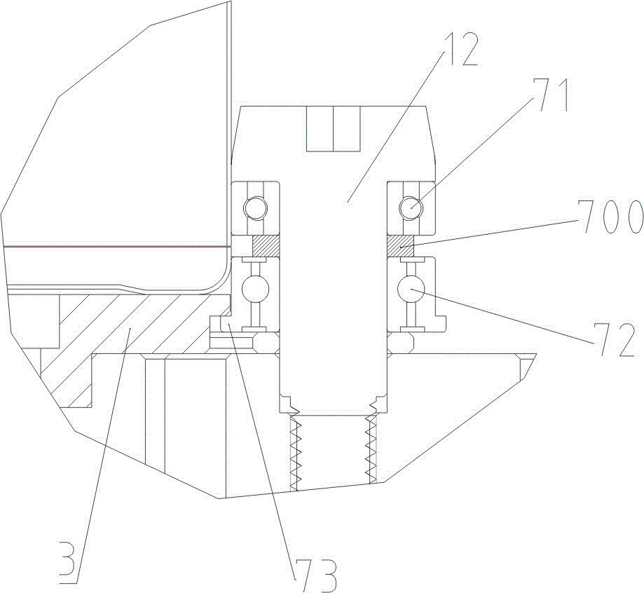
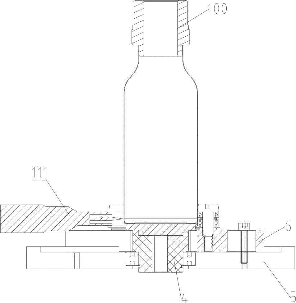
[0027] The present invention will be further described below in conjunction with the embodiments and accompanying drawings (1 to 5).

[0028] The container welding positioning system involved in the present invention sequentially includes a wall body 1, a container bottom cover 2, a lower support plate 3, and a rotating connection block 4. The wall body 1, the container bottom cover 2, the lower support plate 3, and a rotating connection block 4 are coaxial, the section of the wall body 1 and the section of the container bottom cover 2 fit in the circumferential direction, and the wall body 1 and the container bottom cover 2 are docked to form a container to be welded, that is, the welding torch welds the butt joint. The container bottom cover 2 is located between the wall body 1 and the lower support plate 3, the container bottom cover 2 is placed on the end surface of the lower support plate 3, and the rotating connection block 4 is connected to the lower support plate 3. Th...


PUM


Abstract

The invention discloses a container welding positioning system. The container welding positioning system sequentially comprises a wall body, a container bottom cover, a lower supporting plate and a rotating connecting block. The container bottom cover is located between the wall body and the lower supporting plate. The container bottom cover is placed on the end face of the lower supporting plate. The rotating connecting block is fixedly connected with the lower supporting plate. The section of the wall body is attached to the section of the container bottom cover. The rotating connecting block is sleeved with a bottom plate. The rotating connecting block is rotationally connected with the bottom plate. The bottom plate is provided with adjusting sliding blocks in sliding connection with the bottom plate. The adjusting sliding blocks are distributed on the bottom plate in the circumferential direction. Wheel mechanisms are fixedly connected to the adjusting sliding blocks. The wheel mechanisms are rotationally connected with a container. A notch is formed in the bottom plate. The fixing position can be flexibly adjusted according to the size of the container, operation is simple, positioning is accurate, the production cost is reduced, and meanwhile the efficient welding process and the high welding quality are guaranteed.

Description

technical field [0001] The invention relates to container welding, especially a container welding positioning system for bottom welding of thin-walled containers. Background technique [0002] Existing metal containers are generally all made of stainless steel, such as thermos cups, kettles, and electric kettles. The wall thickness of the container is relatively thin, and it is generally made of a thin-walled tube of 0.25-0.8 mm. Because the mouth of the container is smaller than the body of the bottle, the body and bottom of the bottle are generally processed separately, and finally the product is completed by welding the bottom of the bottle. [0003] Existing commonly used welding technology all exists such and such deficiency. For the welding technology using the inner support block of the bottle wall, the inner support block needs to be taken out from the bottle mouth after welding is completed, but since the bottle body is usually larger than the bottle mouth, it is ...

Claims


Application Information

Patent Timeline
Patent Type & Authority Patents(China)
IPC IPC(8): B23K37/053
CPCB23K37/053B23K2101/12
Inventor 程平江
Owner LINGHANG IND & TRADE ZHEJIANG
Why Eureka
Try Eureka