

Feeding mechanism
A technology of feeding mechanism and tray, applied in the direction of conveyor objects, transportation and packaging, etc., can solve the problems of inability to realize automatic circulation of product carriers, affect production costs, and low efficiency of loading and unloading materials, so as to facilitate loading and unloading of product carriers , Easy to take and place the product carrier, and easy to take materials
- Summary
- Abstract
- Description
- Claims
- Application Information
AI Technical Summary
Problems solved by technology
Method used
Image

Examples
Embodiment Construction
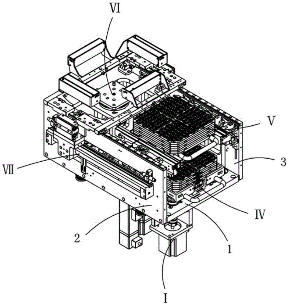
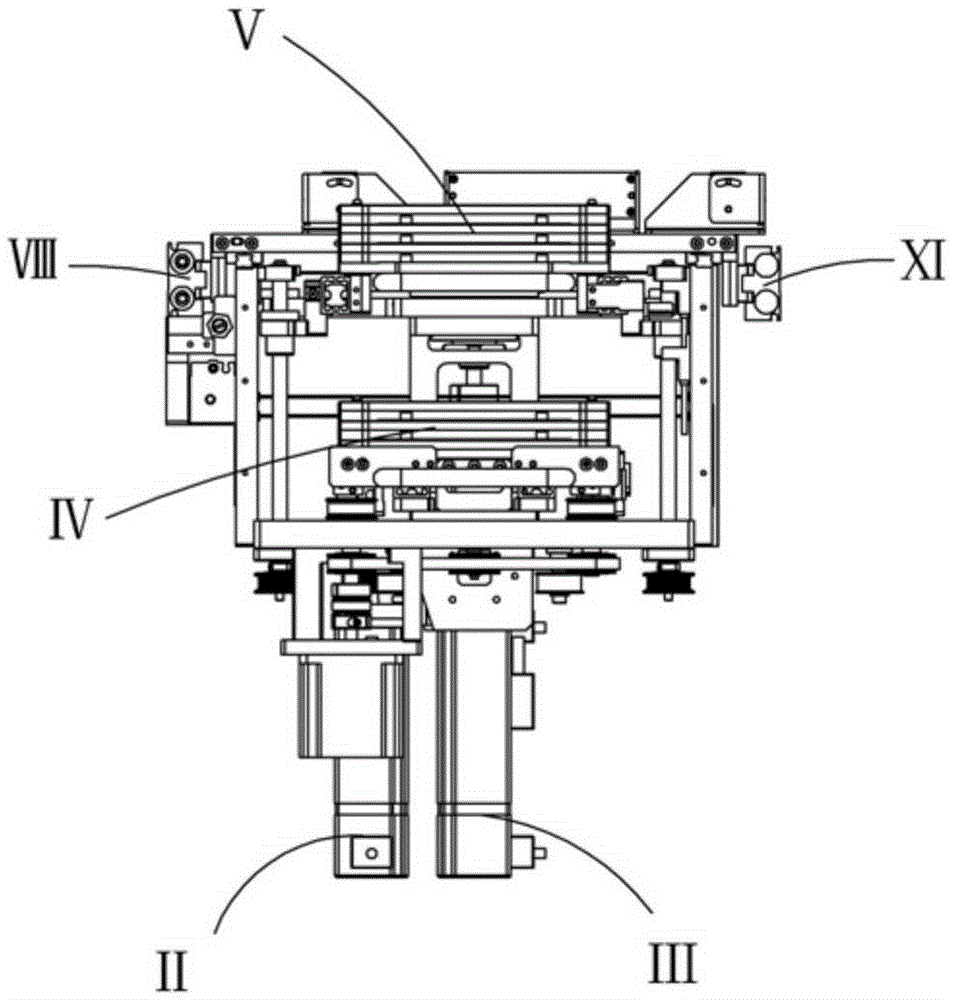
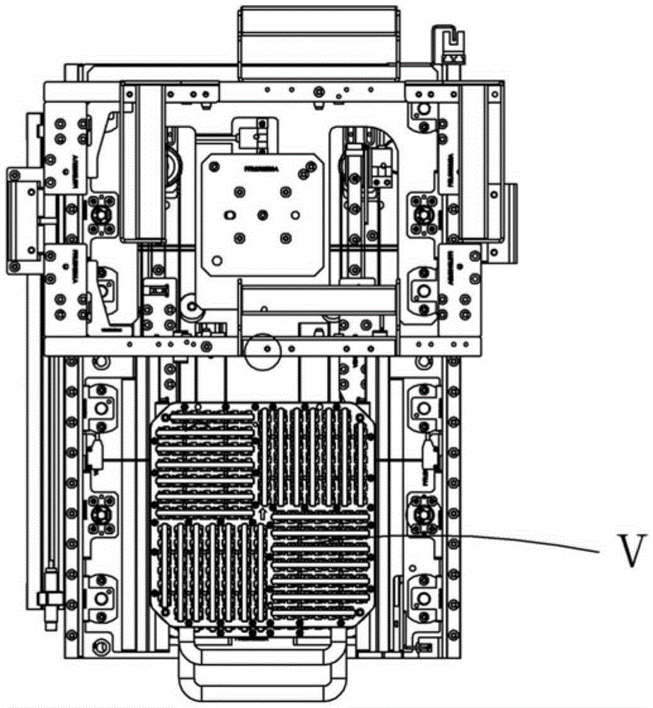
[0038] Examples, see attached Figure 1-15 , a feeding mechanism, the left and right sides of the base plate 1 are respectively equipped with side fixing plates, which are the left fixing plate 2 and the right fixing plate 3, and the translation drive assembly I is installed on the base plate; the base plate and The lifting drive assembly aII and the lifting drive assembly bIII are installed between the left and right fixed plates; the lower tray assembly IV is installed on the upper front side of the bottom plate; the upper tray assembly V is installed on the lift drive assembly a; The above-mentioned lifting drive assembly b is equipped with a rotary feeding assembly VI.
[0039] The translation drive assembly includes a driving motor 4, a driving motor mounting plate 5, a driving motor mounting side plate 6, a driving coupling 7 and a driving driving wheel 8, a driving synchronous wheel 9 and a driving synchronous belt 10, and the driving motor mounting side The plate is i...
PUM
 Abstract
Description
Claims
Application Information