Carrying drive assembly

A technology for handling drive components and components, applied in the direction of conveyor objects, transportation and packaging, etc., can solve the problems of low loading and unloading efficiency, high labor intensity, and affecting production costs, and achieve the effect of convenient material retrieval and space saving

Active Publication Date: 2016-03-16
BOZHON PRECISION IND TECH CO LTD
View PDF8 Cites 5 Cited by
  • Summary
  • Abstract
  • Description
  • Claims
  • Application Information

AI Technical Summary

Problems solved by technology

[0002] The materials in the prior art are generally placed on the product carrier, and sometimes the entire product carrier needs to be transported to the required position or the required height for loading or unloading, but in the prior art, the product carrier is generally transported manua

Method used


Image

  • Carrying drive assembly
  • Carrying drive assembly
  • Carrying drive assembly

Examples


Example Embodiment

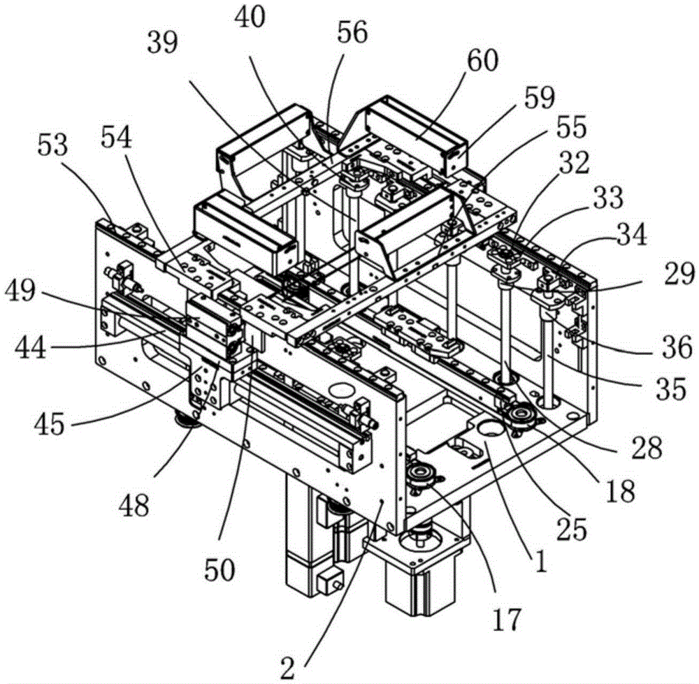
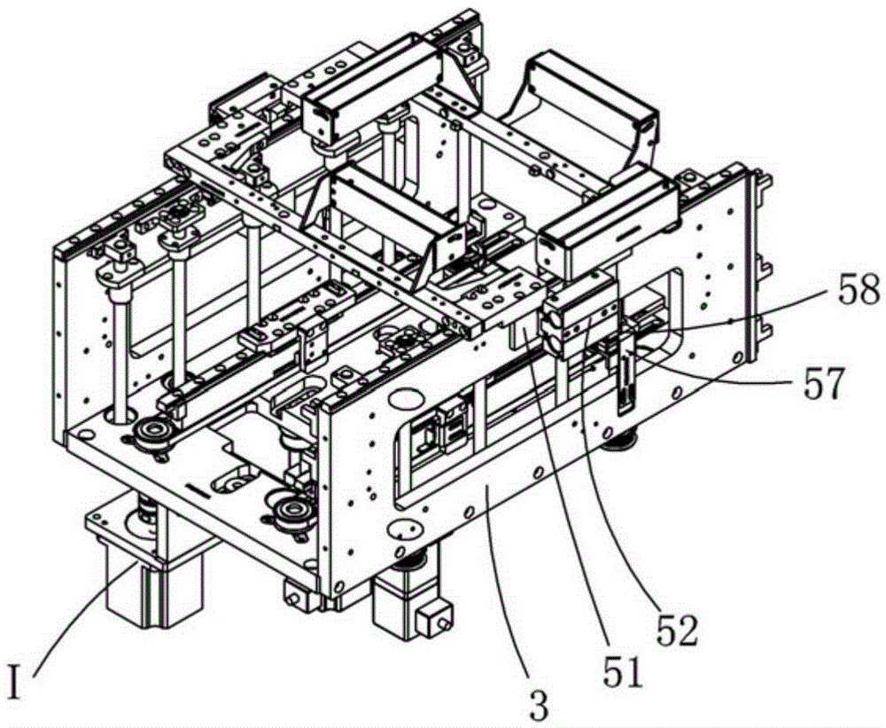
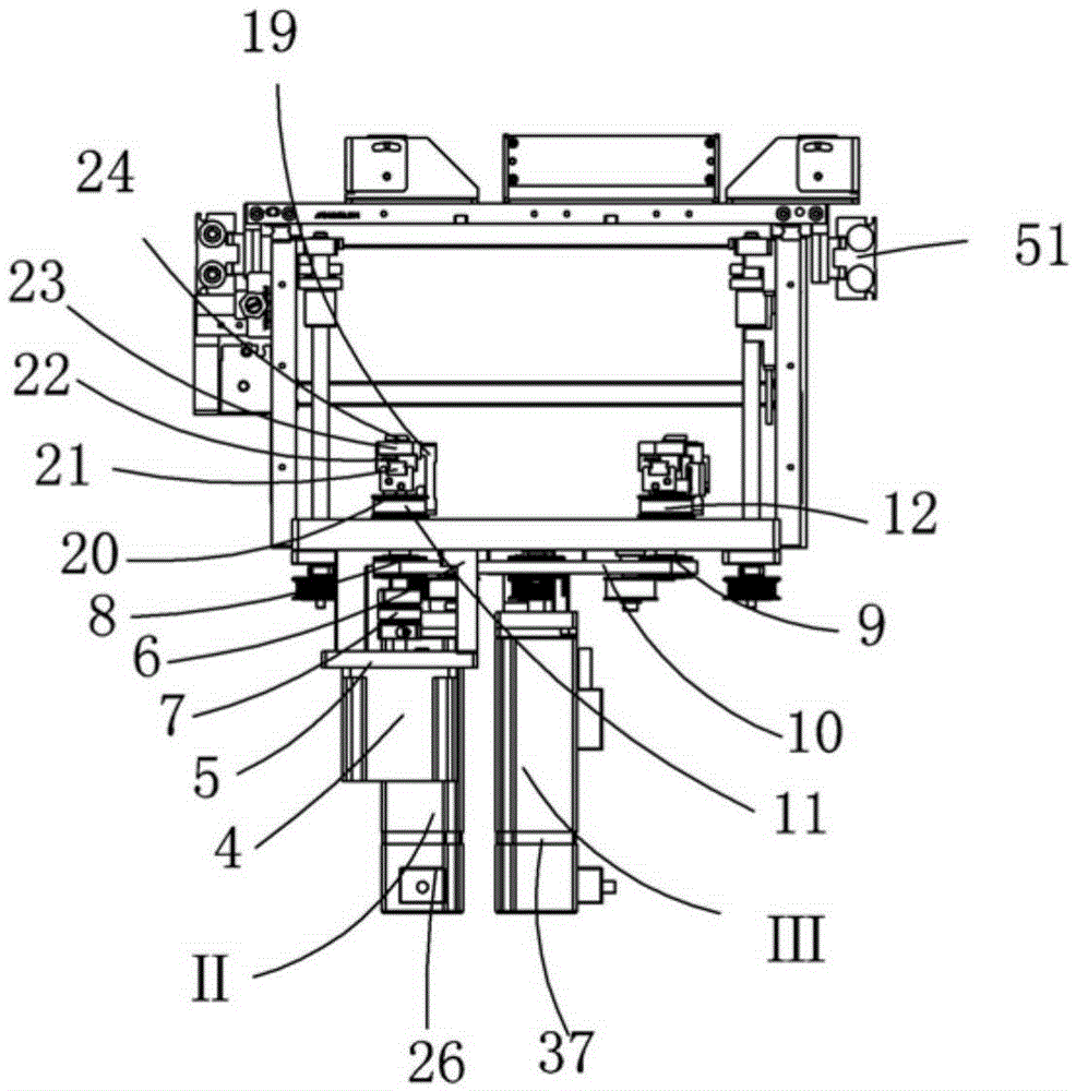
[0024] Examples, see attached Figure 1~6 , A conveying drive assembly, comprising a bottom plate 1, on which the left and right sides of the bottom plate are respectively installed with side fixing plates, the left side fixing plate 2 and the right side fixing plate 3, and the translation drive assembly I is installed on the bottom plate; The translational drive assembly includes a drive motor 4, a drive motor mounting plate 5, a drive motor mounting side plate 6, a drive coupling 7 and a drive driving wheel 8, a drive synchronization wheel 9 and a drive timing belt 10, the drive motor mounting side plate Installed at the bottom of the bottom plate, the drive motor mounting plate is mounted on the lower end of the drive motor mounting side plate, and the drive motor is mounted on the drive motor mounting plate; the main shaft of the drive motor is connected to the drive main shaft through a drive coupling, and is mounted on the drive main shaft There is a driving driving wheel...


PUM


Abstract

The invention relates to a carrying drive assembly. A bottom plate is provided with a left fixing plate and a right fixing plate and provided with a horizontal-moving drive assembly. Lifting drive assemblies are arranged between the bottom plate and the left fixing plate and between the bottom plate and the right fixing plate respectively. A transferring assembly is arranged on the outer side of the left fixing plate and provided with a left carrying tool clamping drive device. The upper portions of the left fixing plate and the right fixing plate are each provided with a sliding rail set. Two sliding block sets are arranged on each sliding rail set. All the sliding block sets on the left fixing plate and the right fixing plate are correspondingly connected with left clamping blocks of the left carrying tool clamping drive device and right clamping blocks of a right carrying tool clamping drive device respectively. Front clamp strips are connected between the sliding blocks in front of the left fixing plate and the right fixing plate. Rear clamp strips are connected between sliding blocks on the rear portions of the left fixing plate and the right fixing plate. By the adoption of the carrying drive assembly, product carrying tools can be moved horizontally and can be driven to ascend and descend, and the front clamp strip and the rear clamp strip can clamp the product carrying tools to convey the product carrying tools to the standard positions.

Description

Technical field: [0001] The invention relates to the field of drive devices, and more specifically relates to a transport drive assembly. Background technique: [0002] The materials in the prior art are generally placed on the product carrier, and sometimes the entire product carrier needs to be transported to the required position or the required height for loading or unloading, but in the prior art, the product carrier is generally transported manually. The tool or handling device can only realize translation or up and down movement, and cannot realize the automatic circulation of the product carrier. The manual operation has high labor intensity and low efficiency, and the loading and unloading efficiency is low, which affects the production cost. Therefore, it is necessary to design a mechanism that can move the product carrier in translation, can realize the product carrier up and down; can clamp the product carrier, and can send the product carrier to the standard po...

Claims


Application Information

Patent Timeline
IPC IPC(8): B65G47/91B65G47/82
CPCB65G47/82B65G47/912
Inventor 吕绍林朱晓锋刘武雷李星
Owner BOZHON PRECISION IND TECH CO LTD
Why Eureka
Try Eureka