Concrete pouring construction method for underground gallery

A construction method and concrete technology, applied in the field of concrete pouring, can solve the problems of high cost of construction materials and difficult control of construction quality, and achieve the effects of shortening the construction period, reducing the construction cost and increasing the turnover rate.

Inactive Publication Date: 2016-03-16
TIANJIN 20 CONSTR
View PDF8 Cites 7 Cited by
  • Summary
  • Abstract
  • Description
  • Claims
  • Application Information

AI Technical Summary

Problems solved by technology

[0003] In order to solve the problems existing in the prior art, the present invention provides a concrete pouring construction method for under

Method used


Image

  • Concrete pouring construction method for underground gallery
  • Concrete pouring construction method for underground gallery

Examples


Embodiment Construction

[0021] The present invention will be described in detail below in conjunction with the accompanying drawings.

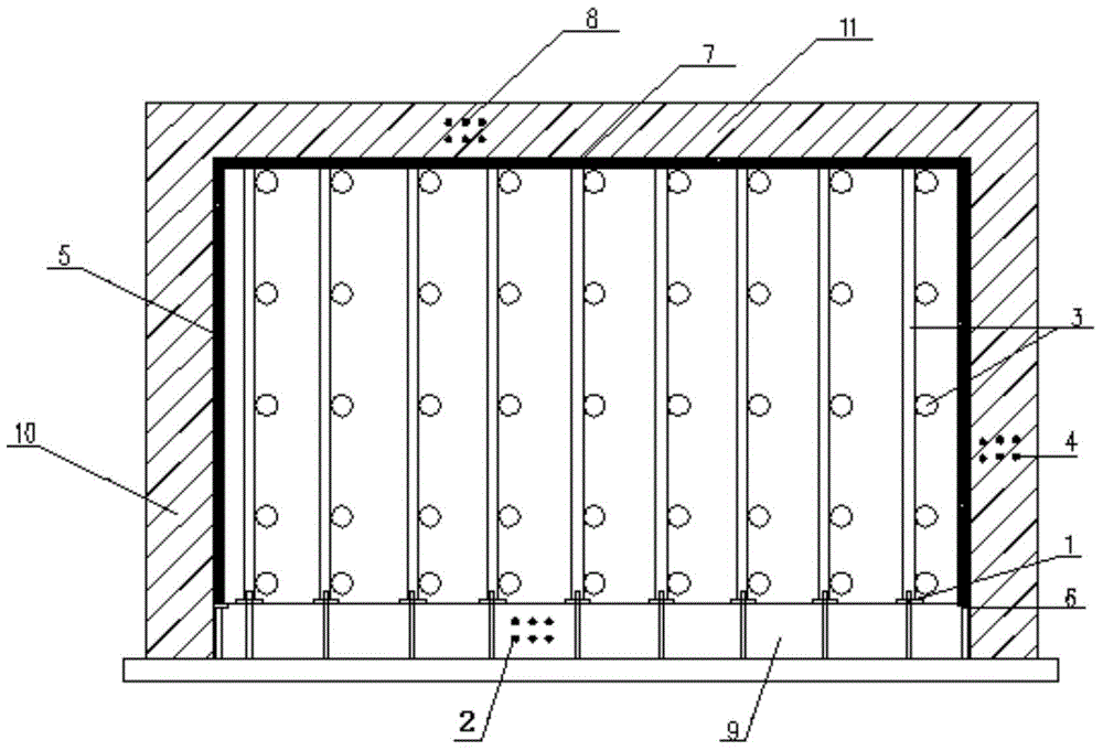
[0022] The concrete pouring construction method of the underground corridor comprises the following steps:

[0023] (1) Project positioning and setting out, earthwork excavation, cushion concrete construction;

[0024] (2) Bottom plate reinforcement 2 binding, welding bracket. After the binding of the steel bars on the bottom plate is completed, the bracket 1 is arranged on the steel bars on the bottom plate according to the spacing requirements of the vertical poles of the scaffolding. The vertical steel bar of the bracket 1 is welded on the steel bar 2 of the bottom plate with the remaining steel bar waste of Φ20, and the welding length on the steel bar of Φ20 is 100mm The Φ14 steel bar is used as the support point for the vertical pole.

[0025] (3) After the side wall reinforcement 4 is bound, weld the reinforcement bracket 6 on the inner side of the junction b...


PUM

PropertyMeasurementUnit
Diameteraaaaaaaaaa

Abstract

The invention discloses a concrete pouring construction method for an underground gallery. The concrete pouring construction method comprises the step of bottom slab concrete pouring, side wall concrete pouring and top slab concrete pouring, an inner formwork and an outer formwork of the side wall are erected to the top at a time, and the step that concrete is poured onto a bottom slab, a side wall and a top slab after scaffolds and top slab formworks are installed completely. Due to the fact that the bottom slab concrete, the side wall concrete and the top slab concrete are poured at a time, stagnant water steel plates do not need to be installed through welding, so that the material cost of the stagnant water steel plates and welding rods as well as the labor cost for welding the stagnant water steel plates are reduced, the turnover rate of the steel formworks and the scaffolds is increased, the construction cost is greatly reduced, and the construction period is shortened; in addition, no horizontal construction seam exists in the wall, and the waterproof performance is improved.

Description

technical field [0001] The invention relates to a concrete pouring method, in particular to a concrete pouring construction method for an underground corridor. Background technique [0002] At present, in the field of industrial construction, especially in areas with high groundwater levels, the control of construction joints and waterproof quality during the concrete construction of underground corridors has always been a difficult problem. The existing construction technology is generally divided into two concrete pourings. Firstly, the bottom plate reinforcement, side wall reinforcement (part) and embedded parts are bound, and the steel plate waterstop (or rubber waterstop) is installed at 200mm-300mm above the sidewall bottom. ), install the formwork, pour concrete for the bottom slab of the underground corridor and 200mm-300mm side wall concrete above the bottom slab, then bind the side wall and roof reinforcement, install the side wall formwork, and pour concrete for t...

Claims


Application Information

Patent Timeline
IPC IPC(8): E02D15/06
Inventor 齐利涛王曰标周锟刘宝生王全常浩宇曹涛马晶晶张轶群
Owner TIANJIN 20 CONSTR
Why Eureka
Try Eureka