Design Method of Turnable Guide Vane in Axial Flow Compressor

A technology of an axial flow compressor and a design method, which is applied to mechanical equipment, components of a pumping device for elastic fluids, machines/engines, etc., can solve the problems of complex regulation and control, complicated design and manufacture, etc. , The effect of reducing design and manufacturing cost and simple structure

Active Publication Date: 2018-02-16
HARBIN TURBINE +1
View PDF5 Cites 0 Cited by
  • Summary
  • Abstract
  • Description
  • Claims
  • Application Information

AI Technical Summary

Problems solved by technology

[0005] The present invention solves the problems of complex design and manufacture and complex adjustment and control of an axial flow compressor unit with all guide vanes rotatable

Method used


Image

  • Design Method of Turnable Guide Vane in Axial Flow Compressor
  • Design Method of Turnable Guide Vane in Axial Flow Compressor
  • Design Method of Turnable Guide Vane in Axial Flow Compressor

Examples


specific Embodiment approach 1

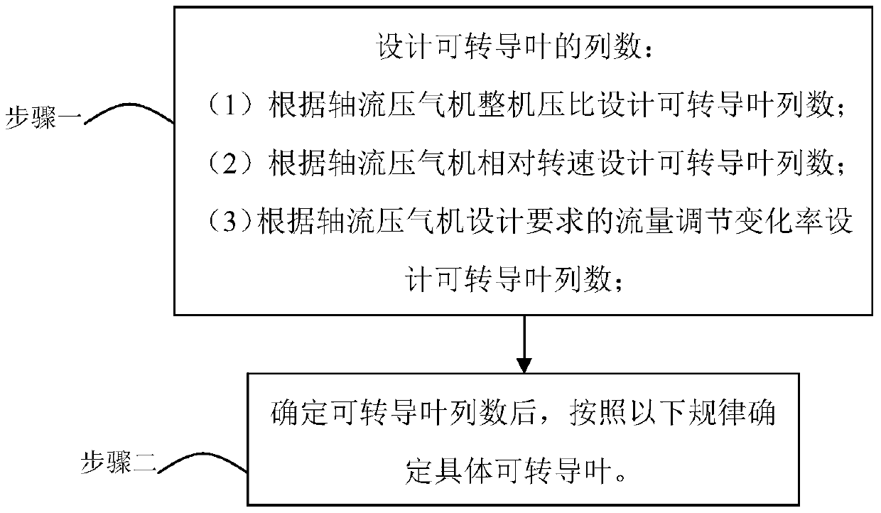
[0042] Specific implementation mode one: combine figure 1 To describe this embodiment,

[0043] The design method of the transmissible guide vane in the axial flow compressor described in this embodiment includes the following steps:

[0044] Step 1. Design the number of columns of transducible leaves:

[0045] From the perspective of start-up acceleration and anti-surge, it is most effective to choose the first few stages of guide vanes to be rotatable; consider the following aspects;

[0046] (1) According to the overall pressure ratio of the axial flow compressor, the number of transmissible vane rows is designed:

[0047] Design the number of transducable vane rows according to the law that the number of transducible vane rows increases with the increase of the pressure ratio of the axial flow compressor;

[0048] (2) According to the relative rotational speed of the axial flow compressor, the number of transformable vane rows is designed:

[0049] According to the rul...

specific Embodiment approach 2

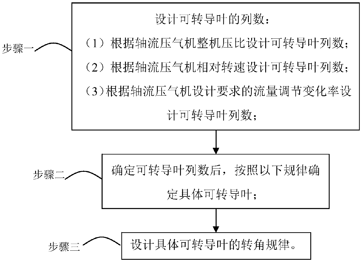
[0062] Specific implementation mode two: combination figure 2 To describe this embodiment,

[0063] The design method for the transmissible guide vane in the axial flow compressor described in this embodiment also includes the following steps:

[0064] Step 3. Design the rotation angle law of the specific transducible vane:

[0065] When the design of two rows of guide vanes can be rotated, that is, the design inlet and the first stage can be rotated; the law of lowering is adopted;

[0066] When the three rows of guide vanes are designed to be rotatable, that is, the design inlet, 1st stage, and 2nd stage are rotatable; the law of lowering is adopted;

[0067] When the four rows of guide vanes are designed to be rotatable, that is, when the design inlet, 1st stage, 2nd stage, and 3rd stage are rotatable; use the rule of lowering or flat adjustment;

[0068] When the five rows of guide vanes are designed to be rotatable, that is, when the inlet, 1st, 2nd, 3rd, and 4th stag...

specific Embodiment approach 3

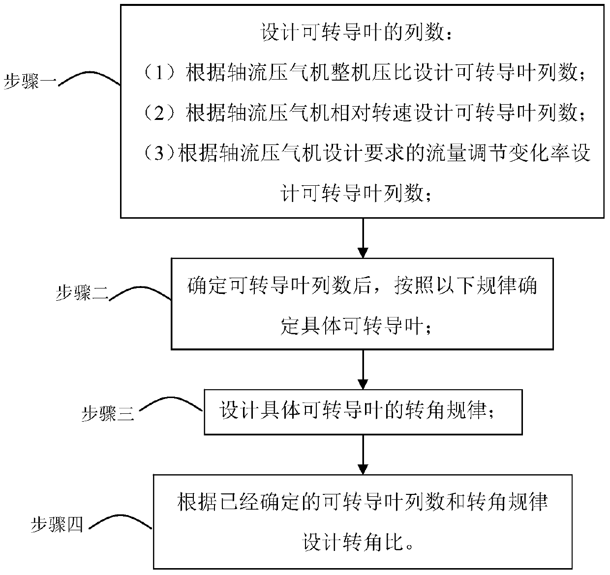
[0076] Specific implementation mode three: combination image 3 To describe this embodiment,

[0077] The design method for the transmissible guide vane in the axial flow compressor described in this embodiment also includes the following steps:

[0078] Step 4. Design the rotation angle ratio according to the determined number of transducible vane rows and the rotation angle law:

[0079] (1-1) When the two rows of guide vanes are rotatable and the down-regulation rule is adopted: the turning angle ratio of the inlet turning guide vanes is 1.0, and the turning angle ratio of the first-stage turning guiding vanes is 0.90-0.97;

[0080] (1-2) When the three rows of guide vanes are rotatable and the down-regulation rule is adopted: the rotation angle ratio of the inlet transmissible vanes is 1.0, the rotation angle ratio of the first-stage transducible vanes is 0.90-0.97, and the second-stage transmissible vanes The corner ratio is 0.80-0.94;

[0081] (1-3) When the four rows...


PUM


Abstract

The invention relates to a design method of a turntable vane in an axial flow compressor, and the invention relates to a design method of a turntable vane. The invention aims to solve the problems of complex design and manufacture and complex adjustment and control of an axial flow compressor unit with all rotatable guide vanes. In the present invention, the number of rows of transducible vanes is firstly designed according to the overall pressure ratio of the axial flow compressor, the relative rotational speed of the axial flow compressor, or the rate of change in flow regulation required by the design of the axial flow compressor; Specific transducible vanes; then design the rotation angle law of specific transducible vanes according to the designed row number of transducible vanes and specific transducible vanes; finally design the rotational angle ratio. The invention is applicable to the design and manufacture of axial flow compressors.

Description

technical field [0001] The invention relates to a design method of a transducible vane. Background technique [0002] High-pressure ratio, large flow, and high-efficiency axial-flow compressors require a wide range of flow changes, a wide range of stable operation, a wide high-efficiency area, and a large pressure ratio safety margin. However, when the axial flow compressor deviates from the design state, the volumetric flow rate of the gas is not suitable for the flow size and the installation angle of the blades, etc., resulting in the separation of the air flow in the cascade flow channel, the deterioration of the operating state of the unit, and even unstable working conditions, which affect normal operation of the unit. In view of the above problems, the following methods are currently used to regulate the flow. [0003] 1. The method of changing the speed is used to adjust the flow rate, but this adjustment method is limited. [0004] 2. Adopt an axial flow compress...

Claims


Application Information

Patent Timeline
Patent Type & Authority Patents(China)
IPC IPC(8): F04D29/54
Inventor 薛恒王景生郑兰琴刘海旭戴博林叶东平冯永志李宇峰张宏涛
Owner HARBIN TURBINE
Why Eureka
Try Eureka