Novel remote control method of pneumatic air valve

A technology of remote control and air valve, which is applied in the direction of valve details, valve devices, engine components, etc., can solve the problems that the air source power supply cannot maintain the opening and closing position of the air valve, and cannot be chained with the fan to control the operation, so as to achieve protection and control accurate effect

Inactive Publication Date: 2016-03-16
JIANGSU JOSUN AIR CONDITIONER
View PDF6 Cites 3 Cited by
  • Summary
  • Abstract
  • Description
  • Claims
  • Application Information

AI Technical Summary

Problems solved by technology

[0003] In order to solve the problems in the prior art that the original opening and closing position of the air valve cannot be maintained due to the disappearance of the air source and power supply, and that the operation cannot be interlocked with the fan, the present invention provides a new type of remote control method for the pneumatic air valve to complete the remote pneumatic air valve. The one-time opening, closing and locking of the valve can meet the combined use of manual and electric control switching, realize the chain control with the fan, and the control is accurate, safe and reliable

Method used


Image

  • Novel remote control method of pneumatic air valve
  • Novel remote control method of pneumatic air valve
  • Novel remote control method of pneumatic air valve

Examples


Embodiment Construction

[0036] Further description will be made below in conjunction with the accompanying drawings.

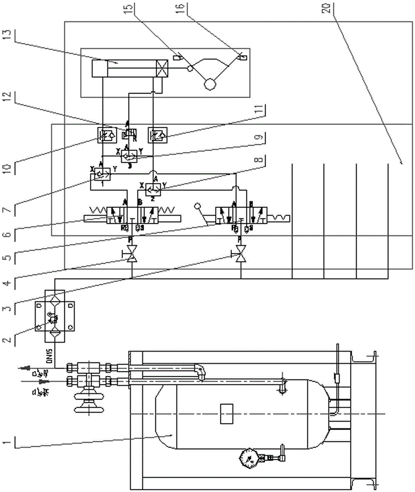
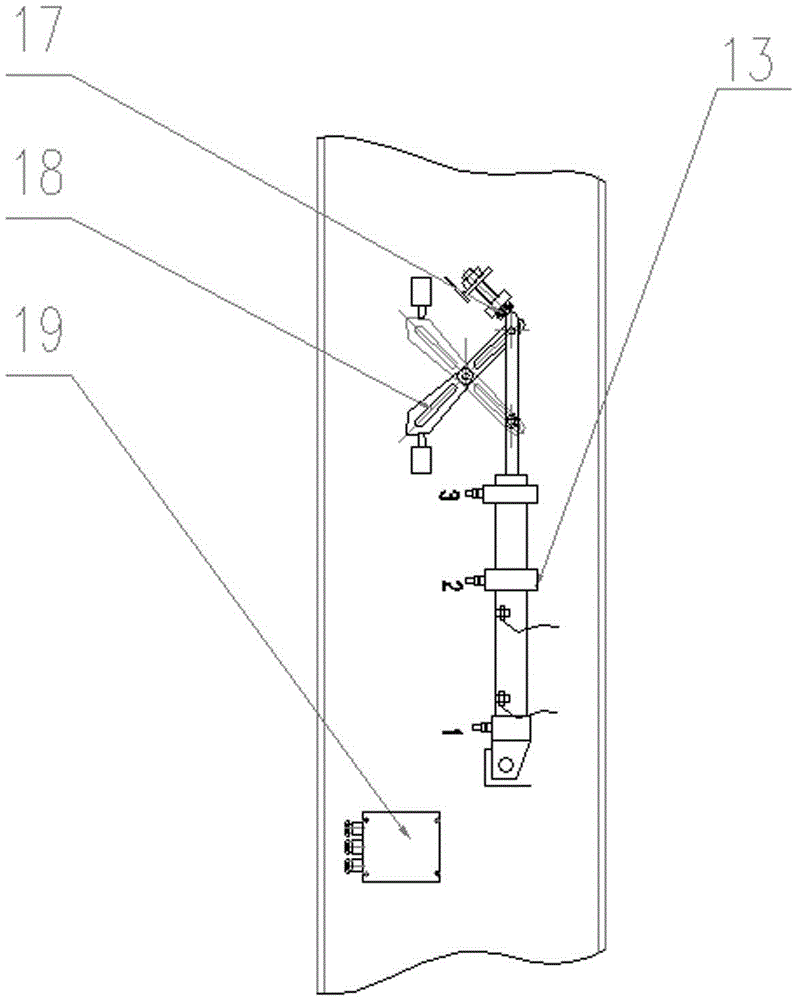
[0037] Figure 1-3 Shown: A new air valve remote control device includes air cylinder 1, pneumatic triple piece 2, manual stop valve 3, electric stop valve 4, three-position five-way hand valve 5, three-position five-way solenoid valve 6, the first shuttle Valve 7, second shuttle valve 8, locking shuttle valve 9, first throttle valve 10, second throttle valve 11, two-position three-way air control valve 12, locking cylinder 13, closing travel switch 15, opening travel switch 16. Nylon stop block 17, lever 18 and junction box 19.

[0038]The air bottle 1 is connected to the manual shut-off valve 3 and the electric shut-off valve 4 respectively in two ways through the pneumatic triple unit 2. Air ports A and B are respectively connected to the first shuttle valve 7-air inlet Y and the second shuttle valve 8-air inlet Y, and the two air outlets A and B of the three-position five-way s...


PUM


Abstract

The invention relates to a novel remote control method of a pneumatic air valve. The method is characterized in that an air bottle is divided into two parts which are correspondingly connected to a manual stop valve and an electric stop valve, wherein the manual stop valve communicates with an air inlet of a three-position five-way hand plate valve; two air outlets of the three-position five-way hand plate valve are correspondingly connected to the air inlet of a first shuttle valve and the air inlet of a second shuttle valve; two air outlets of a three-position five-way solenoid valve are correspondingly connected to another air inlet of the first shuttle valve and another air inlet of the second shuttle valve; the air outlet of the first shuttle valve is divided into two parts which are correspondingly connected to the air inlet of a locking shuttle valve and a first throttling valve; the air outlet of the second shuttle valve is divided into two parts which are correspondingly connected to another air inlet of the locking shuttle valve and a second throttling valve; the first throttling valve communicates with an inner cavity at one end of piston of a locking cylinder, and the second throttling valve communicates with the inner cavity at the other end of the piston of the locking cylinder; the air outlet of the locking shuttle valve communicates with a locking air inlet of the locking cylinder through a two-position two-way pneumatic valve; a cylinder rod of the locking cylinder is used for driving a pneumatic air valve plate through a swinging arm.

Description

technical field [0001] The invention relates to a damper control device, in particular to a method for remote manual and electric control of a pneumatic damper. Background technique [0002] The remote control device of the existing pneumatic air valve adopts a switch type cylinder, which has no locking effect, so that when the air source and power supply disappear, the opening and closing of the pneumatic air valve cannot be realized remotely. That is, it is not possible to open the air valve to exhaust air according to the needs of on-site exhaust air. In some existing remote-controlled pneumatic air valves, the fan is opened first, and the air is exhausted when the air valve is not opened. 1. Insufficiencies such as manual and electric remote control cannot be realized on the same device, and the control performance is poor. Contents of the invention [0003] In order to solve the problems in the prior art that the original opening and closing position of the air valv...

Claims


Application Information

Patent Timeline
IPC IPC(8): F16K31/05F16K31/14
CPCF16K31/05F16K31/14
Inventor 秦伯进王雪红吴坤孙玲焦月红杨卫
Owner JIANGSU JOSUN AIR CONDITIONER
Why Eureka
Try Eureka