Ice making system on refrigerator door

A refrigerator door and ice maker technology, applied in ice making, ice storage/distribution, household refrigeration equipment, etc., to achieve the effect of convenient manufacturing, high ice production efficiency, and not easy to freeze ice

Active Publication Date: 2016-03-16
HEFEI HUALING CO LTD +1
View PDF5 Cites 5 Cited by
  • Summary
  • Abstract
  • Description
  • Claims
  • Application Information

AI Technical Summary

Problems solved by technology

[0004] The technical problem to be solved by the present invention is: in order to solve the horizontal rotation of the ice stirring rod of the ice delivery unit of the existing refrigerator ice machine to push the ice horizontally, the resistance in the ice pushing process is relatively large, and the problem of ice jamming or damage to the ice stirring rod is easy to occur

Method used


Image

  • Ice making system on refrigerator door
  • Ice making system on refrigerator door
  • Ice making system on refrigerator door

Examples


Embodiment 1

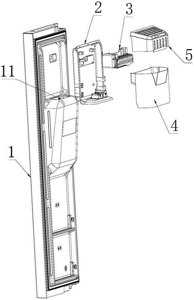
[0058] Such as image 3 , 6 , 7a, this embodiment discloses an ice-making system on the refrigerator door, including:

[0059] The ice maker 3 is installed on the inner side of the refrigerator compartment door 1;

[0060] The ice storage box 4 is installed inside the refrigerator door 1 and below the ice maker 3 for storing ice cubes made by the ice maker 3;

[0061] The distributor is arranged on the outside of the refrigerator door 1, and the distributor is connected with a distribution channel 11 extending to the bottom of the ice storage box 4;

[0062] The top of the ice storage box 4 is open, the ice storage box 4 is provided with a partition 46, and the ice cubes produced by the ice maker 3 are stored in the ice storage box 4 above the partition 46; The partition 46 is used as the bottom of the ice storage box 4, the top of the partition 46 stores ice, and the bottom of the partition 46 discharges ice.

[0063] An ice outlet channel 41 and an ice drop channel 44 ar...

Embodiment 2

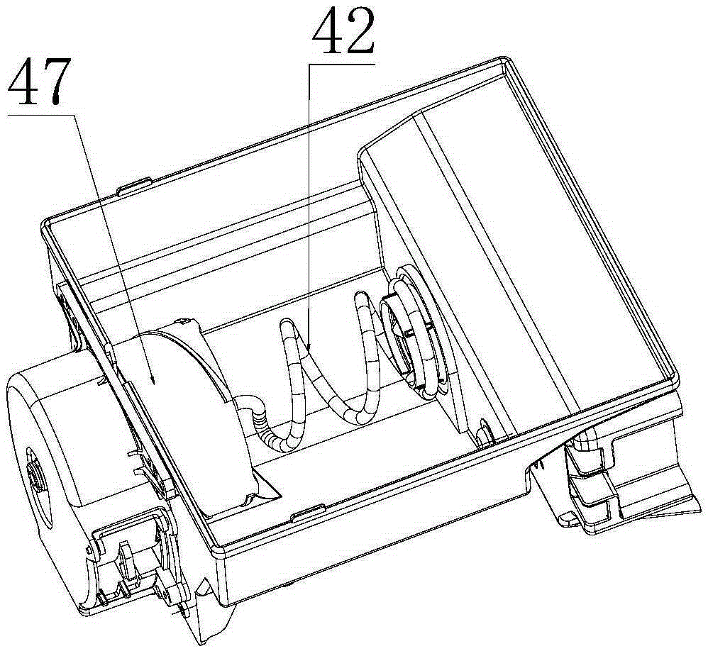
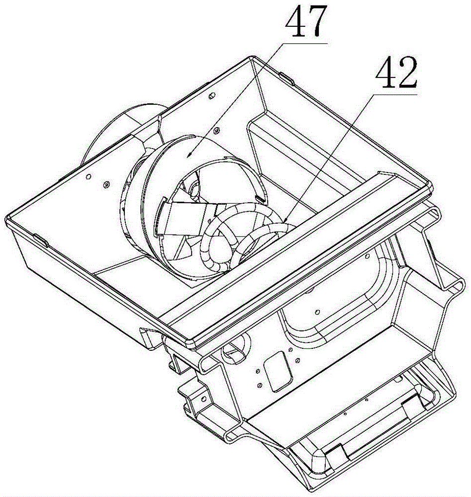
[0081] This embodiment is basically the same as the embodiment, the only difference is: Figure 7a As shown, the ice outlet channel 41 communicates with the ice drop channel 44 at the junction of the side wall and the bottom wall 411, and there is a gap between the side wall of the ice outlet channel and the ice selection cylinder 47 for ice cubes to pass through. The gap is located directly above the ice drop channel 44; the ice selection cylinder 47 is used to pass the ice cubes dropped from the ice inlet 45 through the side wall and bottom wall 411 of the ice outlet channel 41 Push the joint of the ice drop channel 44 into it.

[0082] That is to say, the ice cubes can fall into the ice-falling channel 44 from the bottom surface of the side of the ice-selecting cylinder 47 at the same time. There is a gap in the ice-discharging channel 41, and the gap is located directly above the ice-falling channel 44. The ice cubes in the ice-selecting tube 47 After entering the gap fro...


PUM


Abstract

The invention belongs to the technical field of refrigerator ice making and discloses an ice making system on a refrigerator door. The structure that an ice stirring rod is arranged above a separation board, an ice selection barrel is arranged in an ice discharging channel, and ice is discharged through the side wall or the joint of the side wall and the bottom wall of the ice selection barrel is adopted, the ice stirring rod is vertically arranged, and ice stirring resistance is small. Ice discharging efficiency is high by the adoption of the structure that the ice is discharged from the side wall and the bottom wall at the same time. The ice stirring rod is arranged so that ice blocks can be prevented from being bonded and it can be guaranteed that the ice blocks can be conveyed out. The ice blocks gradually enter the ice selection barrel through an ice inlet and the ice blocking phenomenon is not likely to happen in the ice selection barrel. When the ice blocks are moved to the side wall communicated with an ice falling channel or the joint of the side wall and the bottom wall along with the ice selection barrel, the ice blocks can automatically fall into the ice falling channel, the resistance in the ice discharging process is small, and the ice is not likely to be stuck. The bottom wall is obliquely arranged, so that it is guaranteed that water cannot be accumulated in the ice discharging channel.

Description

technical field [0001] The invention relates to the technical field of refrigerator ice making, in particular to an ice making system on a refrigerator door. Background technique [0002] Such as figure 1 and 2 As shown, in the ice conveying unit of the existing refrigerator ice maker, the ice pushing rod is arranged horizontally, and the ice pushing rod itself is in a spiral shape. The squeezing action between the rod 42 and the inner wall of the ice storage box drives the ice cubes to move, so that the ice cubes are sent into the ice selection cylinder 47 located at one end of the ice stirring rod 42 to realize the purpose of transporting ice. The rotation axis of the ice stirring rod 42 is set horizontally, the ice stirring rod 42 rotates horizontally, pushes the ice horizontally, the resistance received by the ice stirring rod 42 in the rotation process is relatively large, the phenomenon of ice jamming is prone to occur, the failure rate is high, and the motor and the...

Claims


Application Information

Patent Timeline
Patent Type & Authority Applications(China)
IPC IPC(8): F25C5/02F25D23/02
CPCF25C5/02F25D23/02
Inventor 吕正光王浩徐德林
Owner HEFEI HUALING CO LTD
Why Eureka
Try Eureka