Probe position linearization calibration method for on-machine laser measurement

A laser measurement and calibration method technology, applied in computer control, instruments, simulators, etc., can solve the problems of cumbersome calibration process, high precision, and difficult to accurately adjust the installation position of the laser probe, so as to achieve a simple calibration process and easy operation. , the effect of avoiding heavy computation and instability problems

Active Publication Date: 2016-03-16
NANJING UNIV OF AERONAUTICS & ASTRONAUTICS
View PDF6 Cites 36 Cited by
  • Summary
  • Abstract
  • Description
  • Claims
  • Application Information

AI Technical Summary

Problems solved by technology

[0003] The laser probe is installed on the moving spindle of the machine tool through a mechanical clamping mechanism, but the installation posture of the laser probe is difficult to adjust precisely
In order to compensate the measurement error caused by the installation position and deflection angle, the traditional method is to use the position sensitive detector and the specially designed fixture mechanism to manually adjust the beam axis of the laser probe so that it passes through the center of rotation of the rotary body of the probe, but manually The operation of adjusting the beam direction is very inconvenient, and the accuracy is greatly affected by human factors
Later, a V-shaped block was used to calibrate the beam direction of the laser probe, but this method can only solve the installation attitude of the probe, and cannot determine the installation position
In order to obtain the zero position of the beam of the laser probe

Method used


Image

  • Probe position linearization calibration method for on-machine laser measurement
  • Probe position linearization calibration method for on-machine laser measurement
  • Probe position linearization calibration method for on-machine laser measurement

Examples


Embodiment Construction

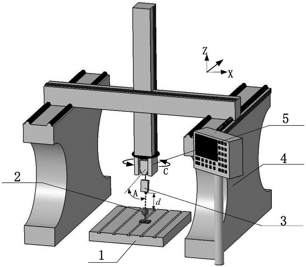
[0028] In order to make the object, technical solution and advantages of the present invention clearer, the present invention will be further described in detail below in conjunction with the accompanying drawings and embodiments. It should be understood that the calibration embodiment described here on the double-swing head five-axis CNC machine tool is only used to explain the present invention, and is not intended to limit the present invention. In addition, the technical features involved in the various embodiments of the present invention described below can be combined with each other as long as they do not constitute a conflict with each other.
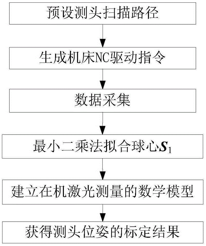
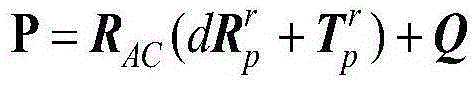
[0029] The basic idea of ​​the present invention is: according to the on-machine measurement mathematical model of the laser probe, the linear equation of the positional relationship between the center of the standard ball and the center of the machine tool coordinate fitting ball is established at multiple rotation angles to re...


PUM


Abstract

The invention discloses a probe position linearization calibration method for on-machine laser measurement. The method comprises steps that, a measurement model of a laser probe moving along with a machine tool is established, a machine tool motion program is generated in an offline mode, the laser probe is driven by the machine tool to carry out multi-angle scanning of a standard ball for ball center fitting, a linear equation group of a standard ball center under multiple machine tool rotation angles and a probe mounting position relationship is acquired, probe mounting position parameters can be acquired through solving the equation group, that a calibration problem is expressed as a nonlinear optimization problem with constraint is not required, and problems of massive calculation and instability existing in nonlinear optimization solution can be avoided.

Description

technical field [0001] The invention belongs to the technical field of on-machine laser measurement, and more particularly relates to a method for calibrating and error compensation of a measuring head installation for on-machine laser measurement. Background technique [0002] The non-contact measurement method represented by laser measurement has the advantages of fast speed, no wear, and no need for probe radius compensation. It can greatly improve the efficiency of measurement while meeting the measurement accuracy, and can obtain more detailed surface information. On-machine measurement can detect problems in manufacturing engineering in time, and then introduce measures such as error compensation to correct these problems in time. An important form of on-machine measurement is to clamp a one-dimensional distance-measuring laser probe at the end of the spindle of a CNC machine tool, drive the laser line from the laser probe to scan the surface of the workpiece through ...

Claims


Application Information

Patent Timeline
IPC IPC(8): G05B19/401
CPCG05B19/4015G05B2219/37008
Inventor 张丽艳夷宏明靳璞磊
Owner NANJING UNIV OF AERONAUTICS & ASTRONAUTICS
Why Eureka
Try Eureka