
Low-voltage grid control system

A control system and low-voltage power grid technology, applied in the direction of AC network voltage adjustment, reactive power compensation, etc., can solve problems such as grid oscillation and overvoltage, and achieve the effect of avoiding grid oscillation or instantaneous overvoltage

Active Publication Date: 2016-03-16
WUHAN CENTURY SUPERPOWER TECH CO LTD
View PDF6 Cites 7 Cited by
  • Summary
  • Abstract
  • Description
  • Claims
  • Application Information

AI Technical Summary

Problems solved by technology

[0005] The main purpose of the present invention is to provide a low-voltage power grid control system, which aims to solve the technical problem that when the power supply line needs to be compensated, each compensation device may act at the same time, so that the power grid oscillates or instantaneous overvoltage occurs

Method used


Image

  • Low-voltage grid control system

Examples


Embodiment Construction

[0019] It should be understood that the specific embodiments described here are only used to explain the present invention, not to limit the present invention.

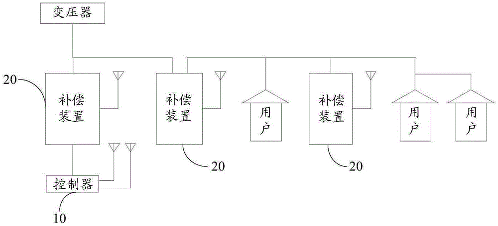
[0020] The invention provides a low-voltage power grid control system, which is applied to the power supply line between the transformer and the user end, and is especially suitable for the power supply line of the low-voltage power grid. The low-voltage power grid control system provided by the invention can be used for distributed hybrid management of power quality. refer to figure 1 , figure 1 It is a schematic diagram of the principle of the low-voltage grid control system of the present invention. The low-voltage grid control system proposed by the present invention includes a controller 10 and at least two compensation devices arranged on the power supply line. The controller 10 and each of the compensation devices 20 connection; the controller 10 determines the compensating devices 20 that need to work and th...


PUM


Abstract

The invention discloses a low-voltage grid control system, applied to a power supply line between a transformer and a user side. The low-voltage grid control system comprises a controller and at least two compensation devices arranged on the power supply line, wherein the controller is connected with each compensation device, and the controller is used for determining the compensation device to be put into work and the working sequence of the compensation device according to the detected electrical parameter signal of the power supply line and for sequentially controlling the determined compensation devices to work according to the determined sequence. Since all the compensation devices adjust respective working parameters according to instructions sent by the controller and the controller sequentially sends instructions to the corresponding compensation devices according to the sequence, all the compensation devices cannot act at the same time ( adjust the working parameters at the same time), thereby effectively avoiding the occurrence of grid turbulence or instant overvoltage.

Description

technical field [0001] The invention relates to the technical field of power grid control, in particular to a low-voltage power grid control system. Background technique [0002] At present, in the power supply line of the low-voltage power grid, the voltage at the outlet terminal of the transformer is often normal, but the voltage at the middle or end of the line is obviously too low, and the voltage amplitude is far lower than the standard value. [0003] In order to solve the above problems, a compensation device is usually installed on the line between the outlet end of the transformer and the user. The compensation device may include, for example, a voltage compensation device, a reactive power compensation device, a harmonic compensation device and / or a three-phase load unbalance compensation device etc. During the power supply process, the compensation device collects electrical parameters such as voltage, current, reactive power, and harmonics in the line, and deter...

Claims


Application Information

Patent Timeline
Patent Type & Authority Applications(China)
IPC IPC(8): H02J3/16
CPCH02J3/16Y02E40/30
Inventor 邢伟孙建军李军华
Owner WUHAN CENTURY SUPERPOWER TECH CO LTD
Learn More