A single live wire switch

A single live wire switch and live wire technology, applied in the field of switches, can solve the problems of weak flickering of energy-saving lamps, potential safety hazards of electricity use, failure to turn off, etc., and achieve the effect of maximizing normal working time

Inactive Publication Date: 2018-07-06
BEIJING HAOHENGTIAN TECH CO LTD
View PDF7 Cites 0 Cited by
  • Summary
  • Abstract
  • Description
  • Claims
  • Application Information

AI Technical Summary

Problems solved by technology

At this time, the electrical equipment cannot be completely disconnected, but a small current flows continuously, which poses a great hidden danger to the safety of electricity consumption.
At the same time, if the electrical equipment is an energy-saving lamp, the weak current will cause the ballast of the energy-saving lamp to work intermittently, causing the energy-saving lamp to flicker weakly and cannot be turned off.

Method used


Image

  • A single live wire switch
  • A single live wire switch

Examples


Embodiment Construction

[0022] Exemplary embodiments of the present disclosure will be described in more detail below with reference to the accompanying drawings. Although exemplary embodiments of the present disclosure are shown in the drawings, it should be understood that the present disclosure may be embodied in various forms and should not be limited by the embodiments set forth herein. Rather, these embodiments are provided for more thorough understanding of the present disclosure and to fully convey the scope of the present disclosure to those skilled in the art.

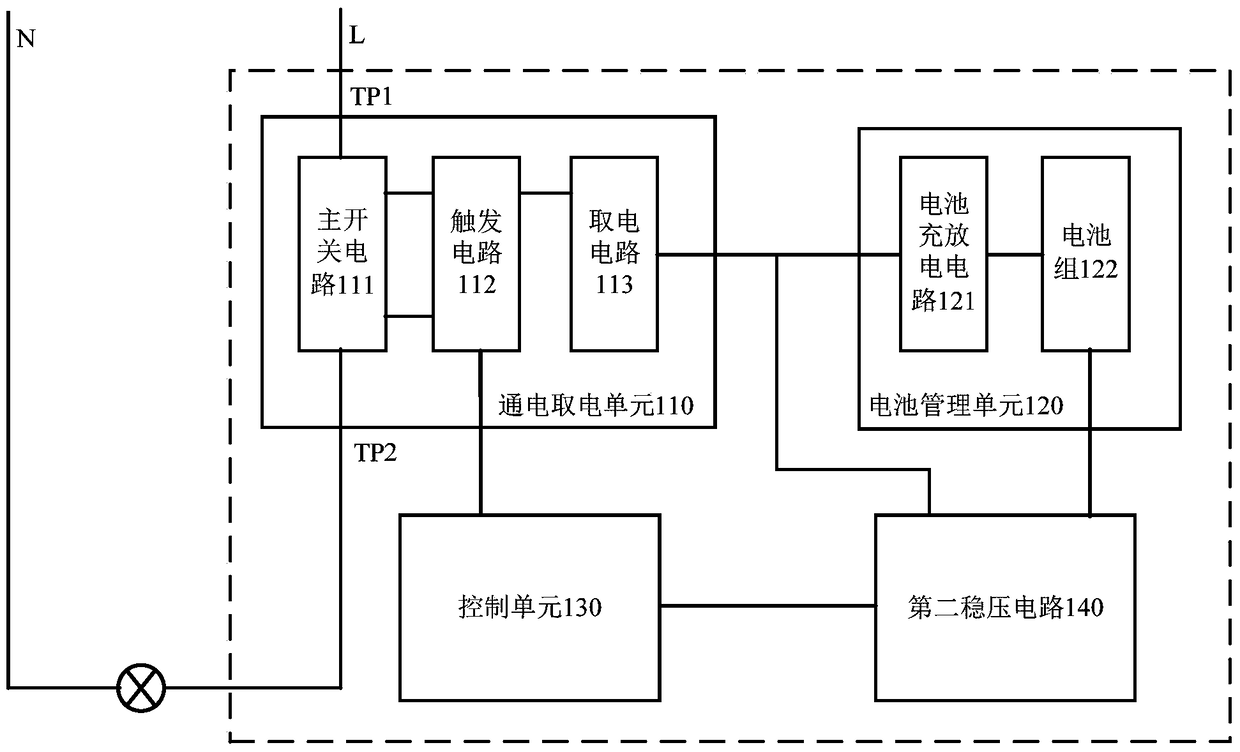
[0023] figure 1 A structural block diagram of a single live wire switch 100 according to an exemplary embodiment of the present invention is shown. The single live wire switch 100 is suitable for realizing the control of electrical equipment in a single live wire environment, such as figure 1 As shown, the input terminal TP of the single live wire switch 100 1 Connect with the incoming line of FireWire L, the output terminal TP ...


PUM


Abstract

The invention discloses a single-livewire switch. The single-livewire switch is suitable for being connected between a livewire and a load and comprises an input end, an output end, a power-on and power-usage unit, a battery management unit and a control unit, wherein the input end is connected with the incoming wire of the livewire; the output end is connected with the load; the power-on and power-usage unit is connected between the input end and the output end and comprises a main switching circuit, a triggering circuit and a power-usage circuit; the main switching circuit is suitable for controlling on and off of the load according to on and off of a main switch; the triggering circuit is suitable for triggering on and off of the main switch; the power-usage circuit is suitable for controlling power supplied to the battery management unit and the control unit according to on and off of the main switching circuit and the triggering circuit; the battery management unit is connected with the power-on and power-usage unit and comprises a battery charging and discharging circuit and a battery pack; the battery charging and discharging circuit is suitable for charging the battery pack when the power-usage circuit supplies power to the battery charging and discharging circuit; the battery pack is suitable for supplying power to the control unit when the battery charging and discharging circuit stops charging; the control unit is respectively connected with the power-on and power-usage unit and the battery management unit; and the control signal end of the control unit is connected with the control signal end of the power-on and power-usage unit.

Description

technical field [0001] The invention relates to the technical field of switches, in particular to a single live wire switch. Background technique [0002] With the continuous maturity of network technology and the rapid development of smart hardware, more and more smart devices have emerged in daily life, which has greatly improved the safety, convenience and comfort of homes, and has also aroused users' interest in smart homes. extensive attention. [0003] In traditional homes, mechanical wall switches are usually used to control electrical equipment. In smart homes, electronic switches generally have remote control or automatic control functions by replacing traditional mechanical wall switches with electronic switches. Intelligent control of equipment can be realized. Electronic wall switches usually include the following parts: power supply unit, control unit, and relay unit. Among them, the power supply unit continuously provides low-voltage DC power to the control ...

Claims


Application Information

Patent Timeline
Patent Type & Authority Patents(China)
IPC IPC(8): H03K17/78H02J7/00
CPCH02J7/0068H03K17/78
Inventor 郎朝见吴天际
Owner BEIJING HAOHENGTIAN TECH CO LTD
Why Eureka
Try Eureka