Fluid-actuated diaphragm drive

A driving device and diaphragm technology, applied in the direction of fluid pressure actuation device, valve operation/release device, valve device, etc., can solve the problems of heavy raw material cost and large driving shell, and achieve rigid optimization and easy cleaning. Effect

Inactive Publication Date: 2017-06-09
FESTO AG & CO KG
View PDF7 Cites 0 Cited by
  • Summary
  • Abstract
  • Description
  • Claims
  • Application Information

AI Technical Summary

Problems solved by technology

However, a suitably small structural volume is only complied with in conjunction with a low actuating pressure, since otherwise a large wall thickness would have to be selected in order to ensure the required structural rigidity, which leads to large external dimensions of the drive housing.
For applications with higher actuating pressures, therefore, a drive housing made of metal is used, which has a high stability even with relatively small wall thicknesses, but in which a large weight and Disadvantages of relatively high raw material costs

Method used


Image

  • Fluid-actuated diaphragm drive
  • Fluid-actuated diaphragm drive
  • Fluid-actuated diaphragm drive

Examples


Embodiment Construction

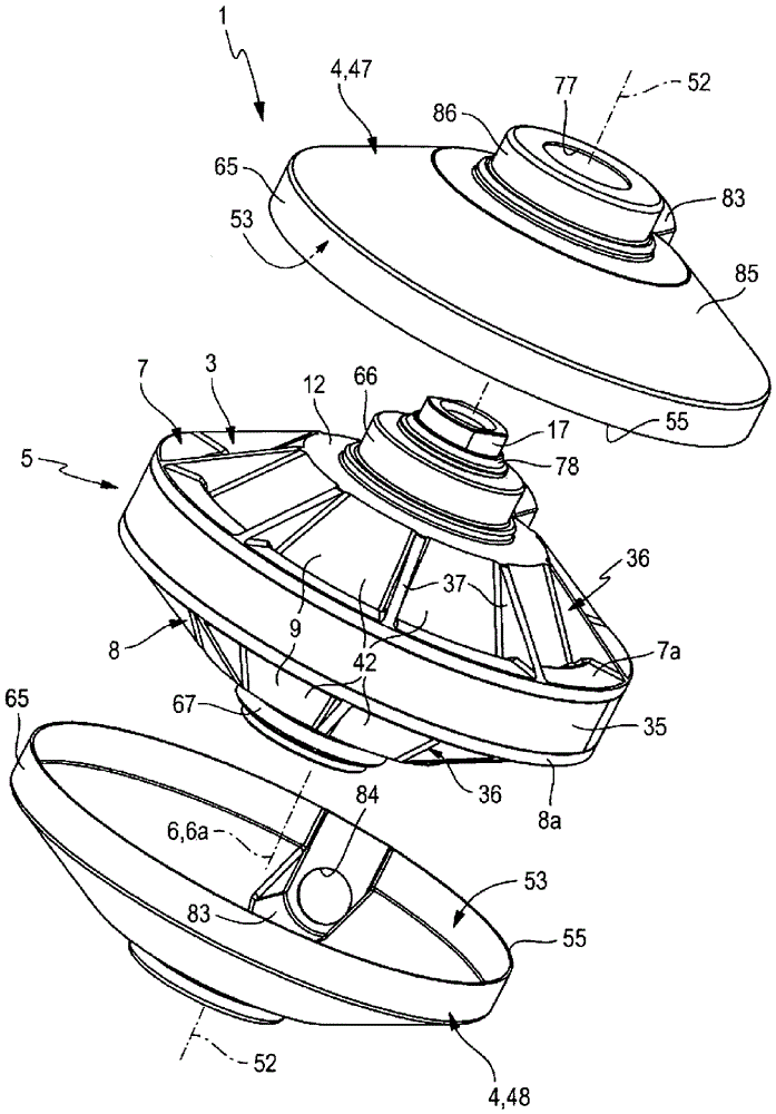
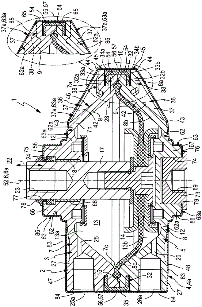
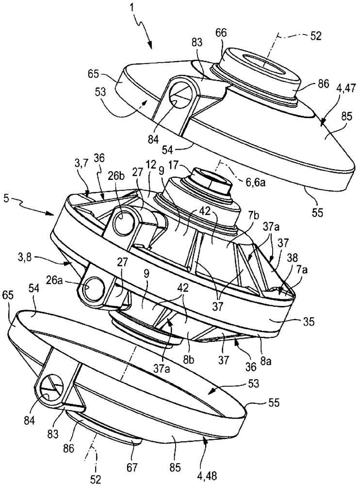
[0031] The diaphragm drive described in its entirety with the reference numeral 1 is of the fluid-actuated type and can be driven by a fluid force provided by a drive medium in a fluid state that can be supplied as required and that can be discharged . Such a drive medium is especially compressed air. However, the diaphragm drive 1 can also be driven by means of another gaseous drive medium or by means of a liquid drive medium.

[0032] The diaphragm drive 1 , which is the housing whose entirety is denoted by reference numeral 2 , has an advantageous hybrid construction with a mixture of plastic material and rust-resistant steel. These materials are distributed, and specifically on the one hand, as a drive housing 3 formed of plastic material and as an enveloping shell 4 of rust-resistant sheet steel surrounding said drive housing 3 . The casing has a protective and support function in order to optimize the use possibilities of the diaphragm drive 1 , which is theoretically ...


PUM


Abstract

The invention relates to a fluid-actuated diaphragm drive (1), which has a drive unit (5), the drive housing (3) of which consists of two cage-shaped drive housings that lie coaxially against each other Pieces (7, 8) are formed. The drive housing (3) is surrounded on the outside by a separate, fluid-tight casing (4) with respect to the drive unit (5), which consists of two casing parts which are mounted against each other and welded to each other in a fluid-tight manner (47, 48), and the cladding shell is formed from rust-proof steel sheets. The cladding shell also forms at the same time support means (4a) clamping said drive housing, by means of which support means the two drive housing parts (7, 8) are supported axially from mutually axially opposite sides, whereby The diaphragm drive ( 1 ) can be operated with high fluid pressure.

Description

technical field [0001] The invention relates to a fluid-actuated diaphragm drive with a drive unit having a longitudinal axis, the drive unit having a drive housing with two hood-shaped drive housing parts made of plastic material, The drive housings are coaxially mounted and fastened against each other with openings facing each other coaxially against each other and fastened against each other under the common delimitation of the housing interior, wherein fluid-tight partitions for the fluid-tight housing interior are arranged in the housing interior. It is the driving diaphragm of two axially adjacent working chambers, the driving diaphragm is connected with the driven rod that can slide through at least one of the driving casings in a transmission manner, and the driving diaphragm passes through The controlled fluid loading of at least one of the working chambers can be axially deflected in order to generate a driven movement of the driven rod. Background technique [00...

Claims


Application Information

Patent Timeline
Patent Type & Authority Patents(China)
IPC IPC(8): F15B15/10F16K31/126
CPCF15B15/10
Inventor H.雷里格
Owner FESTO AG & CO KG
Why Eureka
Try Eureka