
A device for controlling the reaction of a microfluidic chip with a camshaft

A technology of microfluidic chips and camshafts, which is applied in the direction of laboratory containers, laboratory utensils, chemical instruments and methods, etc., can solve problems such as difficult miniaturization and integration, and complicated control devices of microfluidic chips. Achieve the effect of easy productization and wide application prospects

Active Publication Date: 2017-11-28
SHENZHEN HUAMAIXINGWEI MEDICAL TECH CO LTD
View PDF6 Cites 0 Cited by
  • Summary
  • Abstract
  • Description
  • Claims
  • Application Information

AI Technical Summary

Problems solved by technology

[0005] The purpose of the present invention is to solve the problem that the control device of the microfluidic chip is complex, difficult to miniaturize and integrate, and provides a device for controlling the reaction of the microfluidic chip with a camshaft

Method used


Image

  • A device for controlling the reaction of a microfluidic chip with a camshaft
  • A device for controlling the reaction of a microfluidic chip with a camshaft
  • A device for controlling the reaction of a microfluidic chip with a camshaft

Examples


Embodiment Construction

[0017] specific implementation plan

[0018] The invention provides a device for controlling the reaction of a microfluidic chip by using a camshaft. In order to make the object, technical solution and effect of the present invention more clear and definite, the present invention will be further described below in conjunction with the accompanying drawings. It should be understood that the specific embodiments described here are only used to explain the present invention, not to limit the present invention.

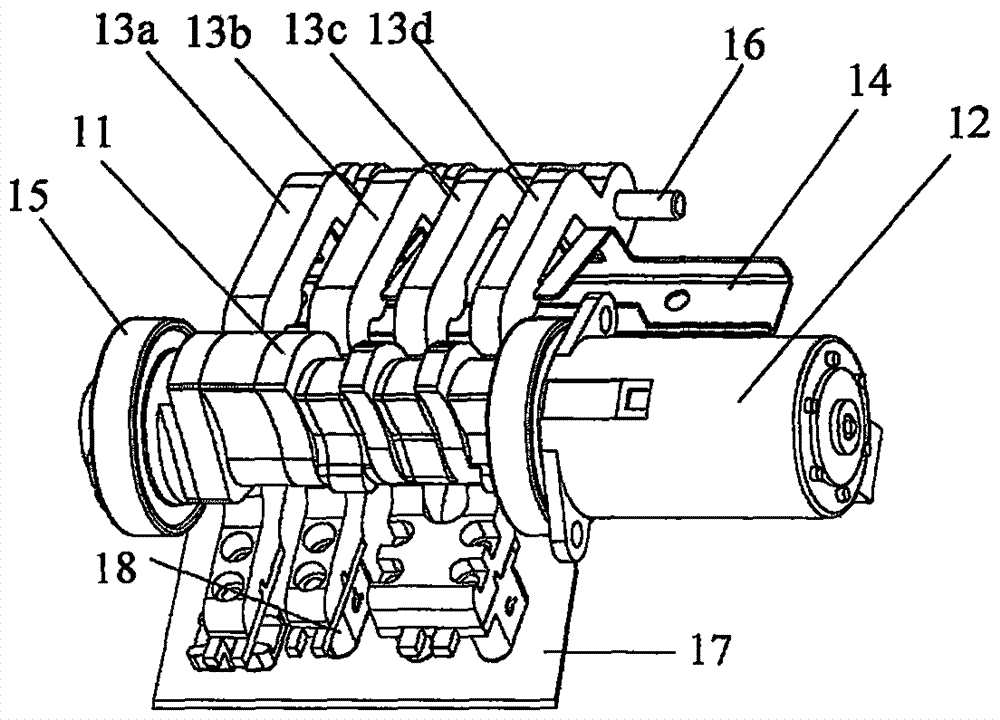
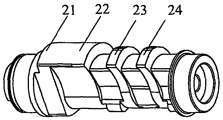
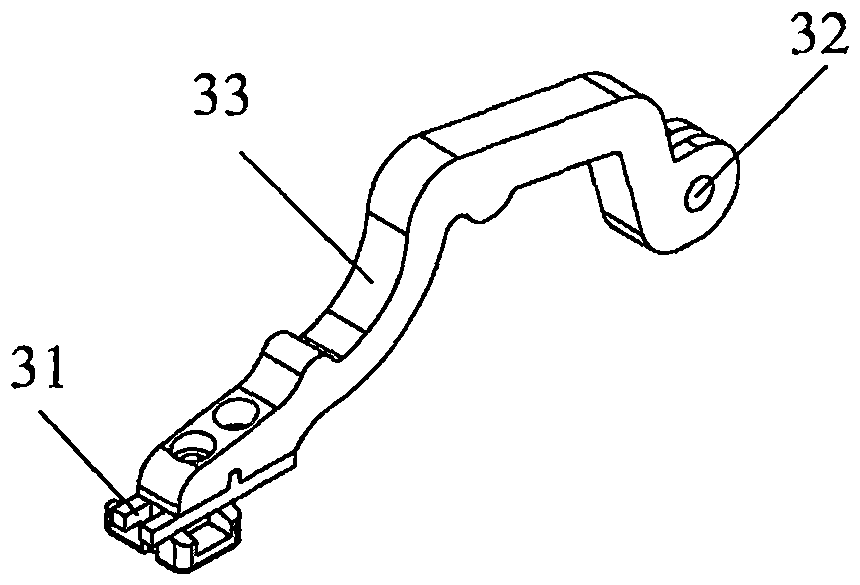
[0019] Such as figure 1 As shown, a device that uses a camshaft to control the reaction of a microfluidic chip, its structure includes a camshaft 11 , a motor 12 , a rocker arm group 13 , a metal shrapnel 14 and a rolling bearing 15 . The main body of the camshaft 11 is a cylinder on which a plurality of cams are arranged in sequence. One end of camshaft 11 is fixed on the output shaft of motor 12, and a rolling bearing 15 is housed on the other end. One end of the ro...


PUM


Abstract

The invention discloses a device for controlling the reaction of a microfluidic chip by using a camshaft. The device uses a camshaft with multiple cams to control multiple links in the reaction process of the microfluidic chip that need to be driven by pressure, such as the time-sharing release and flow control of various liquid reagents in the chip, gas The flow control, as well as the chip locking and other functions that need to be realized by mechanical pressing, the timing of the reaction can be automatically controlled by the curve profile of the cam, the installation sequence, and the rotation speed. The invention provides a feasible technical solution for the miniaturization of the analysis and detection device of the microfluidic chip, making it easier to be commercialized and having wider application prospects.

Description

technical field [0001] The invention belongs to the field of microfluidic chips, in particular to a device for controlling the reaction of a microfluidic chip with a camshaft. Background technique [0002] Microfluidic chip, also known as Lab-on-a-chip (Lab-on-a-chip), refers to the integration of basic operating units such as sample preparation, reaction, separation, and detection involved in the fields of biology, chemistry, and medicine into a chip with On the micron-scale microchannel chip, the whole process of reaction and analysis is automatically completed. The advantages of the analysis and detection device based on the microfluidic chip are: the amount of sample used is small, the analysis speed is fast, and it is easy to make a portable instrument, which is very suitable for instant and on-site analysis. [0003] The core of the analysis and detection device based on the microfluidic chip is the control of the fluid in the microchannel, and pressure drive is one o...

Claims


Application Information

Patent Timeline
Patent Type & Authority Patents(China)
IPC IPC(8): B01L3/00
Inventor 姜润华李泉
Owner SHENZHEN HUAMAIXINGWEI MEDICAL TECH CO LTD
Learn More