Rubber rolling device for producing soft polyurethane (PU) skylight sun shield

A sun visor and roller glue technology, which is applied to the surface coating liquid device, coating, etc., can solve the problems that the amount of glue cannot be adjusted locally, and the glue is easy to penetrate, so as to solve the problem of glue penetration, high efficiency, and less waste Effect

Active Publication Date: 2016-03-23
YANTAI ZHENGHAI HIGH TECH
View PDF7 Cites 0 Cited by
  • Summary
  • Abstract
  • Description
  • Claims
  • Application Information

AI Technical Summary

Problems solved by technology

[0007] The purpose of this application is to solve the problem that in the production process of soft PU sunroof sunshade, in the thin area of ​​the product, the back side is easy to see through the glue, and the current roller glue method cannot adjust the glue amount locally.

Method used


Image

  • Rubber rolling device for producing soft polyurethane (PU) skylight sun shield
  • Rubber rolling device for producing soft polyurethane (PU) skylight sun shield
  • Rubber rolling device for producing soft polyurethane (PU) skylight sun shield

Examples


Embodiment 1

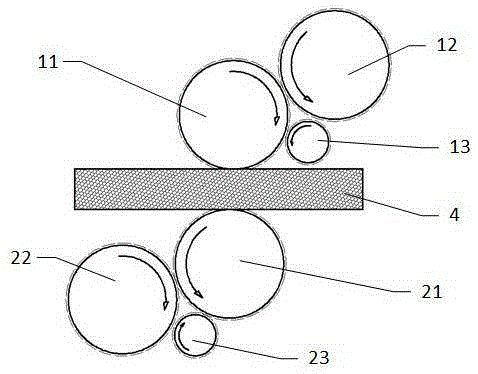
[0026] like Figure 4 As shown, the roller rubber device of the soft PU sunroof sunshade includes two sets of rollers, the upper roller includes the first rubber roller 11 and the second rubber roller 12, the lower roller includes the first rubber roller 21 and the second rubber roller 22, and the PU board 4 is located between the two sets of rollers, and the upper and lower surfaces are in contact with the first rubber rollers 11 and 21 respectively. On the following group of rollers, a third rubber roller 23 is also provided. The first rubber roller and the second rubber roller rotate in opposite directions, and the glue liquid passes through the gap between the two rubber rollers and transfers to the PU board. The rotation direction of the third rubber roller is also opposite to that of the first rubber roller, and a smaller gap is kept, so that a part of glue is trapped between the first rubber roller and the third rubber roller, so that less glue is transferred to the PU...

Embodiment 2

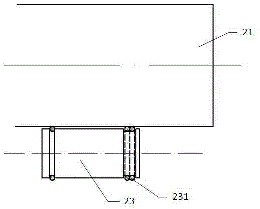
[0031] like Image 6 As shown, the third rubber roller 23 is arranged at a position close to the second rubber roller 22 . The glue liquid accumulated between the first rubber roller 21 and the third rubber roller 23 can be taken away by the second rubber roller 22, and returns to the glue storage area formed by the top of the first rubber roller 21 and the second rubber roller 22, be reused to prevent the glue solution intercepted by the third rubber roller 23 from being wasted.

[0032] If the 3rd cot roller is set between the first cot roller 11 and the second cot roller 12 of upper surface gluing, be subjected to the influence of the space formed by the second cot roller 12 below and the first cot roller 11 and the PU foam board 4 limit, the diameter of the third rubber roller must be very small.

[0033] In this embodiment, the third rubber roller 23 is arranged on the lower group of rollers, the space is sufficient, and the diameter is not limited, and a rubber roller ...

Embodiment 3

[0035] like Figure 7 As shown, the third rubber rollers 13 and 23 are respectively arranged on the upper and lower two groups of rollers, and the amount of rubber rollers on the front and back sides of the PU foam board can be adjusted respectively, and the degree of freedom of process adjustment is greater.

[0036] By adopting the technical scheme of the present application, the glue coming out from the gap formed by the first rubber roller and the second rubber roller contacts with the third rubber roller, and the amount of glue is reduced, which can prevent the sunroof sun visor from showing through on the back side when the thickness of the sunshade is very thin. glue phenomenon. The design of the third rubber roller close to the second rubber roller can take away the glue retained by the third rubber roller by the second rubber roller. The length of the third rubber roller is short, the number may be more than one, and the position and number may be adjusted according ...


PUM


Abstract

The invention relates to a rubber rolling device for a polyurethane (PU) foam board for a soft PU skylight sun shield. The rubber rolling device comprises a first rubber roller and a second rubber roller and further comprises a third rubber roller, wherein a certain seam is kept between the first rubber roller and the second rubber roller, and a certain seam is kept between the first rubber roller and the third rubber roller; the third rubber roller is used for reducing the amount of rubber on a partial area of the first rubber roller. After the third rubber roller is arranged, the amount of rubber can be partially reduced through a rubber rolling method so that the problem of partial rubber penetration of the back face in production of the soft PU skylight sun shield can be solved.

Description

technical field [0001] This application relates to the production technology of automotive interior parts, in particular to a device for rolling glue for PU foam boards used in the production of soft PU sunroof sunshades. Background technique [0002] Soft PU sunroof sunshade, structure as attached figure 1 As shown, from the surface layer to the back layer, there are fabric 1, first isolation film 2, first glass fiber 3, PU foam board 4, second glass fiber 5, and back layer non-woven fabric 6 in sequence. [0003] The production method is that the PU foam board 4 is double-sided coated with polyurethane foam glue and sprayed with water, and then according to the fabric 1, the first isolation film 2, the first glass fiber 3, the PU foam board 4 coated with glue on both sides and sprayed with water, the first 2. The glass fiber 5 and the back non-woven fabric 6 are placed in the hot mold in sequence, kept under pressure for a period of time, and then the mold is opened. In ...

Claims


Application Information

Patent Timeline
Patent Type & Authority Applications(China)
IPC IPC(8): B05C1/08
CPCB05C1/0834
Inventor 朱维珍李海帆丁明秋
Owner YANTAI ZHENGHAI HIGH TECH
Why Eureka
Try Eureka