Mine lot solid waste screening device

A solid waste and screening device technology, applied in the direction of solid separation, separation of solids from solids with airflow, chemical instruments and methods, etc., can solve the problems of waste, high production cost, difficult separation, etc., and achieve low cost and good structure And the effect of simple operation and reducing the amount of impurities

Inactive Publication Date: 2016-03-23
JIANGSU EFFORT TECH & DEV
View PDF5 Cites 2 Cited by
  • Summary
  • Abstract
  • Description
  • Claims
  • Application Information

AI Technical Summary

Problems solved by technology

Solid waste in mining areas is usually used as filling material for mine filling experiments (such as experiments on cylinders, boxes, potted plants, etc.) and field section experiments. Therefore, it is very necessary to screen and classify solid wastes in mining areas with different particle sizes; in addition, solid wastes in mining areas may contain specific substances, and it would be a pity to mix them with other impurities for treatment. It is difficult to separate a specific substance from a pile of impurities, and it would be very wasteful if left unattended
[0003] At present, the solid waste particle size screening devices are mainly vibrating screens and pneumatic sieves. The vibrating screen equipment is bulky and noisy, and is not suitable for transfer; the pneumatic sieve has a complex structure and is not easy to transport. It can only screen a single particle size and cannot better meet the filling requirements of the mine. The requirements for screening solid wastes of different particle sizes during experiments, field profile experiments, laboratory sample analysis and sorting processes; in addition, the above two screening devices are complicated to operate, high in production costs, and usually need to be connected to a power supply during work, and the use of space is limited. Unsuitable working environment for solid waste screening during field sampling in mining areas

Method used


Image

  • Mine lot solid waste screening device
  • Mine lot solid waste screening device

Examples


Embodiment Construction

[0013] The present invention will be further described in detail below in conjunction with the drawings.

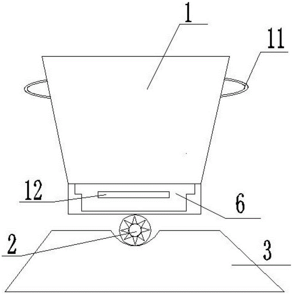
[0014] Such as Figure 1 to Figure 2 As shown, a mining area solid waste screening device includes a screening box 1, a rotating shaft 2, a base 3, and a movable screening door 4. The upper center of the base 3 is provided with a fixed groove, and the rotating shaft 2 is placed in the fixed groove Inward rolling, the screening box 1 is placed on the rotating shaft 2;

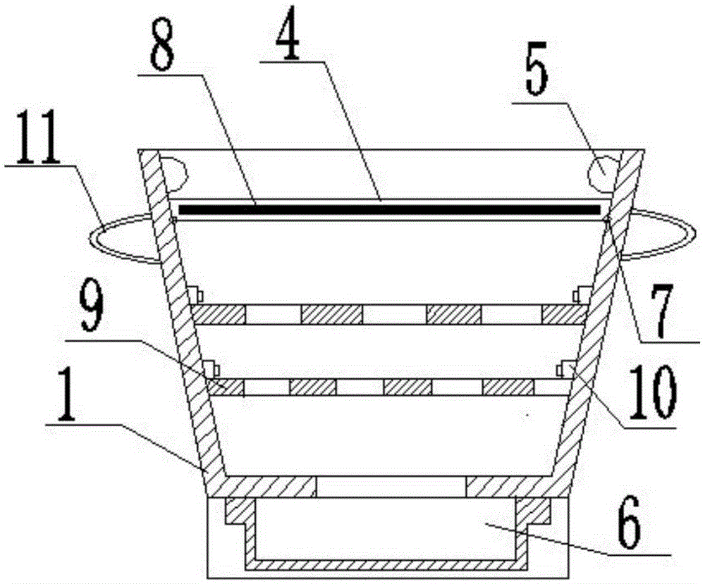
[0015] A substance sensor 5 is provided on the inner wall of the open upper end of the screening box 1; a hole is provided at the bottom of the screening box 1, and a drawer 6 is provided directly below the bottom; both sides of the screening box 1 Handle Ⅰ11 symmetrically;

[0016] The movable screening door 4 is installed at the opening of the upper end of the screening box 1 through a hinge 7; an electromagnet 8 is arranged in the movable screening door 4, and a screening net 9 is arranged directly under the ...


PUM


Abstract

A mine lot solid waste screening device comprises a screening box (1), a rotary shaft (2), a base (3) and a movable screening door (4). A fixing groove is formed in the center of the upper end of the base, the rotary shaft is placed in the fixing groove to roll, and the screening box is placed on the rotary shaft. Substance inductors (5) are arranged on the inner wall of an opening in the upper end of the screening box. A hole is formed in the bottom of the screening box and a drawer (6) is formed under the bottom of the screening box. Handles I (11) are symmetrically arranged on the two sides of the screening box. The movable screening door is installed on the opening in the upper end of the screening box. An electromagnet (8) is arranged in the movable screening door and screening nets (9) are arranged under the electromagnet. The screening nets are installed in the screening box through fixing supports (10). The substance inductors are arranged on the mine lot solid waste screening device, if a specific substance is induced, an operator disposes impurities, and therefore the required substance can be separated out quickly. In addition, the mine lot solid waste screening device is simple in structure and operation, low in manufacturing cost and capable of screening out solid waste of different particle sizes.

Description

Technical field [0001] The invention relates to the field of ore screening equipment, in particular to a mining area solid waste screening device. Background technique [0002] During the mining of coal resources, a large amount of solid waste will be produced. The solid waste in the mining area has complex components and different particle sizes. Solid wastes in mining areas are usually used as filling materials for mining area filling experiments (such as column, box, potted plants, etc.) and field profile experiments. Filling experiments in different mining areas, field profile experiments, and laboratory sample analysis and classification treatment of solid waste particles Diameter requirements are different. Therefore, it is necessary to screen and classify the solid wastes of different particle sizes. In addition, the solid wastes of mining areas may contain specific substances. It is a pity if they are mixed with other impurities for processing. Certain substances are dif...

Claims


Application Information

Patent Timeline
Patent Type & Authority Applications(China)
IPC IPC(8): B07B9/00
CPCB07B9/00
Inventor 时春苗
Owner JIANGSU EFFORT TECH & DEV
Why Eureka
Try Eureka