Plasma cutting fume processing system and method for spiral welded steel pipe

A technology of spiral welding and processing system, applied in the field of welding fume purification, can solve the problems of affecting operation, difficult to achieve, smoke and dust, etc., and achieve the effect of solving the asynchronous change, reducing the passing resistance and expanding the dust collection area.

Active Publication Date: 2017-10-17
BC P INC CHINA NAT PETROLEUM CORP +2
View PDF8 Cites 0 Cited by
  • Summary
  • Abstract
  • Description
  • Claims
  • Application Information

AI Technical Summary

Problems solved by technology

The difficulty in choosing this position is that the dust suction device interferes with the cutting device 5, which affects the operation.
In addition, during the cutting process of the steel pipe, the incision is small, and it is difficult to control the smoke and dust in the steel pipe and flow out from the incision. There will be a lot of smoke and dust at both ends of the steel pipe, especially when the diameter, length and welding speed of the steel pipe change. ,difficult to realize
This method is not currently used in spiral welded pipe enterprises
[0006] The third such as image 3 As shown, in this kind of dust collection position, because the dust collection port needs to move as the steel pipe advances, almost all pipe manufacturers use mobile dust collection hoods 1, the difficulty lies in the steel pipe 6 absorbing while moving, and the stability requirements of the synchronization of the two High, and part of the pipes are connected by hoses, the stretching and bending of the pipes will affect the vacuuming effect
At present, this kind of vacuuming method has a high failure rate of equipment and poor effect

Method used


Image

  • Plasma cutting fume processing system and method for spiral welded steel pipe
  • Plasma cutting fume processing system and method for spiral welded steel pipe
  • Plasma cutting fume processing system and method for spiral welded steel pipe

Examples


Embodiment Construction

[0028] The present invention will be further described below in conjunction with the accompanying drawings and embodiments.

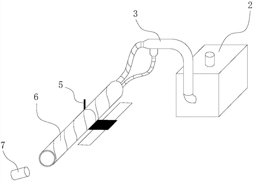
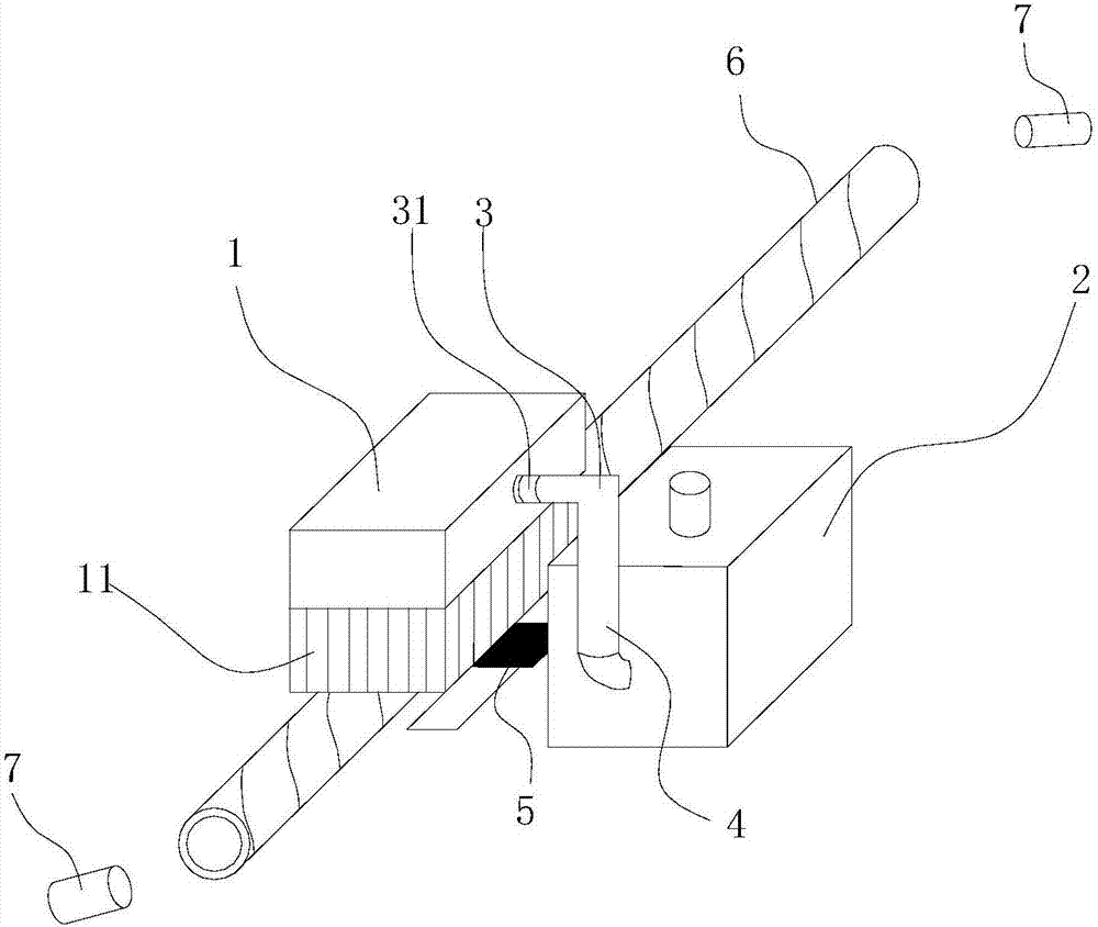
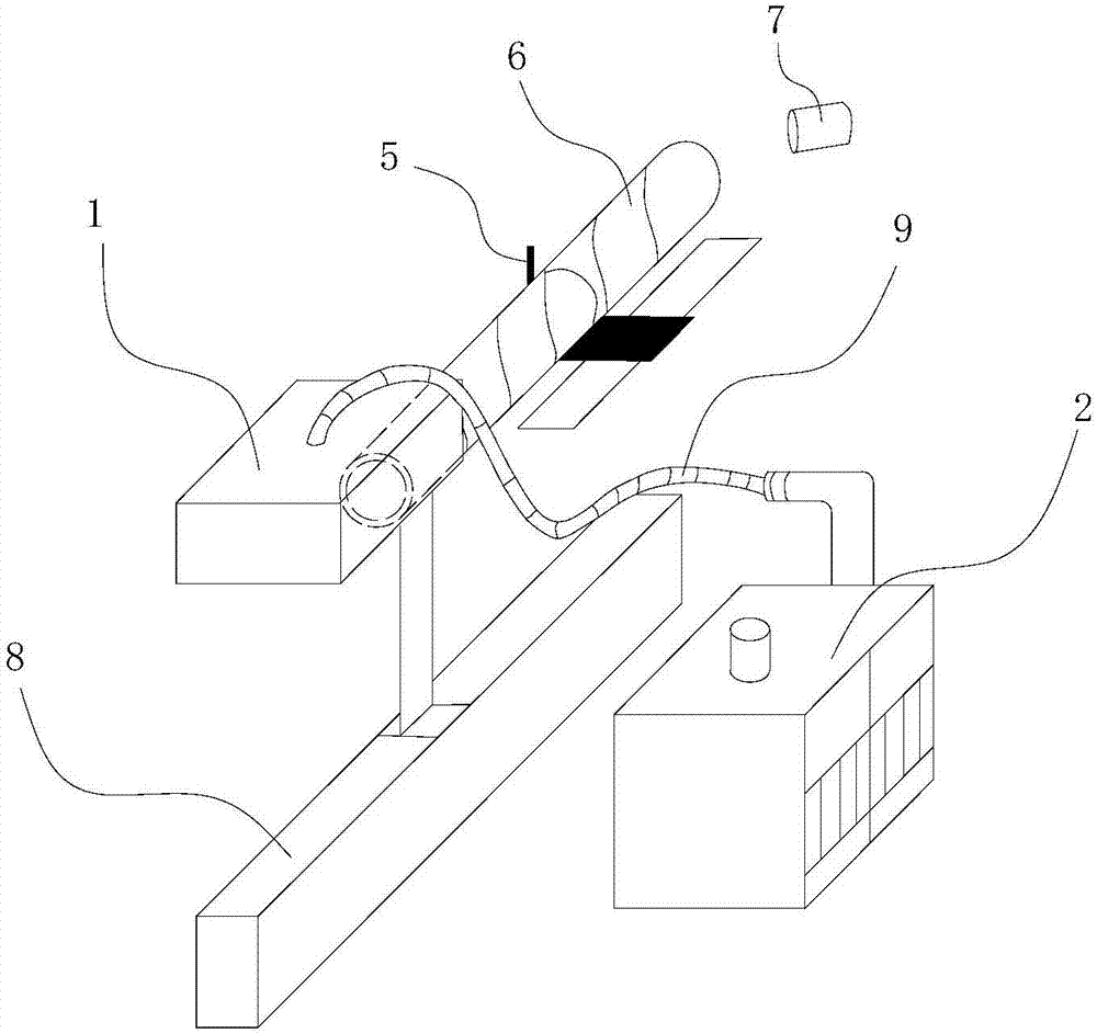
[0029] Such as Figure 4 As shown, the spiral welded steel pipe plasma cutting fume treatment system of the present invention includes: a dust collection cover 1, a dust removal host 2, and a blower 7; the spiral welded steel pipe plasma cutting fume treatment system also includes a rigid dust removal pipe 3;

[0030] The lower surface of the dust collection hood 1 is provided with at least two suction ports; the dust suction ports are evenly distributed along the length direction of the dust collection hood 1; the lower surface of the dust collection hood 1 is surrounded by a soft fireproof curtain 11; The dust removal host 2 has an air outlet 24 and a dust suction main pipe 4;

[0031] The dust suction port of the dust collection hood 1 communicates with the dust suction main pipe 4 through the dust removal pipe 3; the dust suction port corresponds t...


PUM


Abstract

The invention discloses a spiral-welded steel pipe ion cutting smoke treatment system capable of improving the dust removing efficiency and preventing the dust dispersion and being provided with good popularity. The smoke treatment system comprises a dust sucking cover and a dust removing host machine; the spiral-welded steel pipe ion cutting smoke treatment system further comprises a rigid dust removing pipe; two dust sucking ports are at least formed in the lower surface of the dust sucking cover; the dust sucking ports are uniformly distributed in the length direction of the dust sucking cover; fireproof soft curtains are arranged around the lower surface of the dust sucking cover; the dust removing host machine is provided with an exhaust port and a dust sucking main pipe; the dust sucking ports of the dust sucking cover are communicated with the dust sucking main pipe through dust removing pipes; the dust sucking ports and the dust removing pipes are corresponding one to one; and valves are arranged on the dust removing pipes. The invention further discloses a method for treating smoke by using the smoke treatment device. The device and the method, provided by the invention, can improve the smoke sucking efficiency, are excellent in popularity, and can prolong the service life of a filter barrel.

Description

technical field [0001] The invention relates to the field of welding fume purification, in particular to a fume treatment system for plasma cutting of spiral welded steel pipes and a fume treatment method using the system. Background technique [0002] It is well known that there are many types of pollutants produced during the welding process, which are harmful and can cause various occupational diseases (such as welder's silicosis, manganism, electro-optic ophthalmia, etc.). [0003] At present, there are three most commonly used plasma cutting and recycling stations for spiral welded pipes, the 2# beam position (tail), the middle (middle) of the steel pipe, and the head (head) of the steel pipe are as follows: figure 1 , 2 , 3 shown. [0004] The first such as figure 1 As shown, it is a vacuuming position commonly used at present. The principle is to install a blower 7 on the head of the steel pipe 6, and use the method of "blowing at one end and sucking at the other e...

Claims


Application Information

Patent Timeline
Patent Type & Authority Patents(China)
IPC IPC(8): B08B15/02B01D46/00B01D50/00B01D53/26B01D53/02
CPCB01D46/00B01D50/00B01D53/02B01D53/261B08B15/02
Inventor 刘云刘成坤刘伟唐坤
Owner BC P INC CHINA NAT PETROLEUM CORP
Why Eureka
Try Eureka