Supercharge Your Innovation With Domain-Expert AI Agents!

Multifunctional plate bending machine with lifting pressing type pipe bending mechanism

A plate bending machine and pipe bending technology, which is applied to metal rolling mill stands, manufacturing tools, metal rolling racks, etc., can solve the problems of high price, single function, and bulky

Inactive Publication Date: 2016-03-23
CHUZHOU PINZHIDA ELECTRIC TECH
View PDF6 Cites 0 Cited by
  • Summary
  • Abstract
  • Description
  • Claims
  • Application Information

AI Technical Summary

Problems solved by technology

[0002] At present, the plate bending machines on the market need to meet the processing requirements of different sizes of sheet metal, resulting in relatively large volume, heavy weight, high price, and relatively simple functions.

Method used


Image

  • Multifunctional plate bending machine with lifting pressing type pipe bending mechanism
  • Multifunctional plate bending machine with lifting pressing type pipe bending mechanism
  • Multifunctional plate bending machine with lifting pressing type pipe bending mechanism

Examples


Embodiment 1

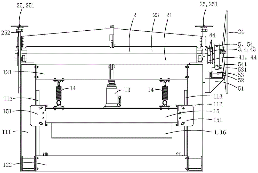
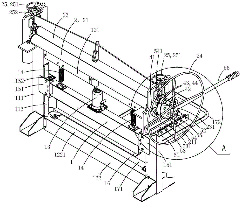
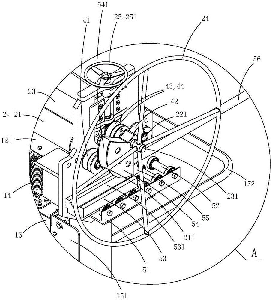
[0015] Figure 1 to Figure 5 A first embodiment of the invention is shown in which, figure 1 It is a structural schematic diagram of the first structure of the present invention; figure 2 yes figure 1 A schematic diagram of a three-dimensional structure of the bending machine shown; image 3 yes figure 2 The partial enlarged schematic diagram of A in the plate bending machine shown; Figure 4 yes figure 1 A schematic diagram of the three-dimensional structure of the bending machine shown when viewed from another angle; Figure 5 yes Figure 4 The partial enlarged schematic diagram of B in the plate bending machine shown.

[0016] This embodiment is a multifunctional plate bending machine, see Figure 1 to Figure 5 As shown, it includes a plate bending mechanism 1, a plate rolling mechanism 2 and a pipe bending mechanism 3; the plate bending mechanism includes a left pillar 111, a right pillar 112, a first horizontal fixed beam 121, a second horizontal fixed beam 122,...

Embodiment 2

[0031] Figure 6 to Figure 8 A second embodiment of the invention is shown, in which Figure 6 It is a structural schematic diagram of the second structure of the present invention; Figure 7 yes Figure 6 A schematic diagram of a three-dimensional structure of the bending machine shown; Figure 8 yes Figure 6 A schematic diagram of the three-dimensional structure of the plate bending machine shown when viewed from another angle.

[0032] This embodiment is basically the same as Embodiment 1, the difference is: see Figure 6 to Figure 8 As shown, the present embodiment also includes a shearing mechanism 6; the shearing mechanism includes a shearing knife 61 and a shearing auxiliary knife 62, the blade 611 of the shearing knife is V-shaped, and the top wall of the shearing auxiliary knife is provided with The V-shaped edge groove 621 adapted to the blade of the shearing horizontal knife; the shearing horizontal knife 61 is rotatably arranged on the I-beam, and the shearing ...


PUM


Abstract

The invention discloses a multifunctional plate bending machine with a lifting pressing type pipe bending mechanism. The multifunctional plate bending machine with the lifting pressing type pipe bending mechanism comprises a plate bending mechanism, a plate milling mechanism and the lifting pressing type pipe bending mechanism. The lifting pressing type pipe bending mechanism comprises a fixed cushion supporting part fixedly arranged on the outer wall of a right supporting heel, a multi-wheel linear sliding rail arranged on the fixed cushion supporting part, a sliding cushion supporting part arranged on the multi-wheel linear sliding rail, a fan-shaped wheel rotationally arranged on a rotary shaft of a third driving roll, a sleeve ring arranged on the fan-shaped wheel and a lifting pressing handle arranged on the fan-shaped wheel. The multi-wheel linear sliding rail, the sliding cushion supporting part and the fan-shaped wheel are located between the right supporting pillar and an annular rotary handle; one linear edge of the sleeve ring adjoins one linear edge of the fan-shaped wheel. The multifunctional plate bending machine with the lifting pressing type pipe bending mechanism achieves multiple functions in one machine.

Description

technical field [0001] The invention belongs to the technical field of mechanical processing, and in particular relates to a multifunctional plate bending machine with a lifting and pressing type pipe bending mechanism. Background technique [0002] At present, the plate bending machines on the market need to meet the processing requirements of different sizes of sheet metal, resulting in relatively large volume, heavy weight, high price, and relatively simple functions. Contents of the invention [0003] The object of the present invention is to provide a multifunctional plate bending machine with a lifting and pressing type pipe bending mechanism. [0004] The technical solution for realizing the purpose of the present invention is: a multifunctional plate bending machine with a lifting and pressing type pipe bending mechanism, including a plate bending mechanism, a plate rolling mechanism and a lifting and pressing type pipe bending mechanism; the plate bending mechanis...

Claims


Application Information

Patent Timeline
IPC IPC(8): B21D5/01B21D5/04B21D7/08B21D7/06B21B1/38B21B31/24B23D15/08
Inventor 刘开成
Owner CHUZHOU PINZHIDA ELECTRIC TECH
Features
  • R&D
  • Intellectual Property
  • Life Sciences
  • Materials
  • Tech Scout
  • Unparalleled Data Quality
  • Higher Quality Content
  • 60% Fewer Hallucinations
Learn More