
Molding machine without sand filling dead angles and application method thereof

A molding machine, no sand filling technology, used in molding machines, casting molding equipment, manufacturing tools, etc., can solve the problems of easy deformation of sand molds, insufficient sand filling, insufficient filling, etc., to increase the spray effect, improve the yield, The effect of reducing dead space

Active Publication Date: 2016-03-23
ZONSAN MACHINERY CO LTD
View PDF6 Cites 12 Cited by
  • Summary
  • Abstract
  • Description
  • Claims
  • Application Information

AI Technical Summary

Problems solved by technology

[0004] Existing molding machines also have double-sided sand shooting, which are usually placed symmetrically to ensure that the two ends can be filled with sand, but there may be cases where the sand is not filled or cannot be filled in the middle, especially when multiple molds are placed at one time. There is always uneven gravel filling in dead corners
[0005] At the same time, due to the deep groove structure of some molds, the deep concave ratio in the compaction process is very large. When it exceeds a certain threshold, the compaction at the bottom of the deep concave is difficult to guarantee; the uncompacted sand mold Easily deformed or even collapsed during transportation and overturning

Method used


Image

  • Molding machine without sand filling dead angles and application method thereof
  • Molding machine without sand filling dead angles and application method thereof
  • Molding machine without sand filling dead angles and application method thereof

Examples


Embodiment Construction

[0030] The present invention will be further described in detail below with reference to the drawings and specific embodiments.

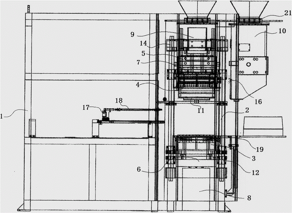
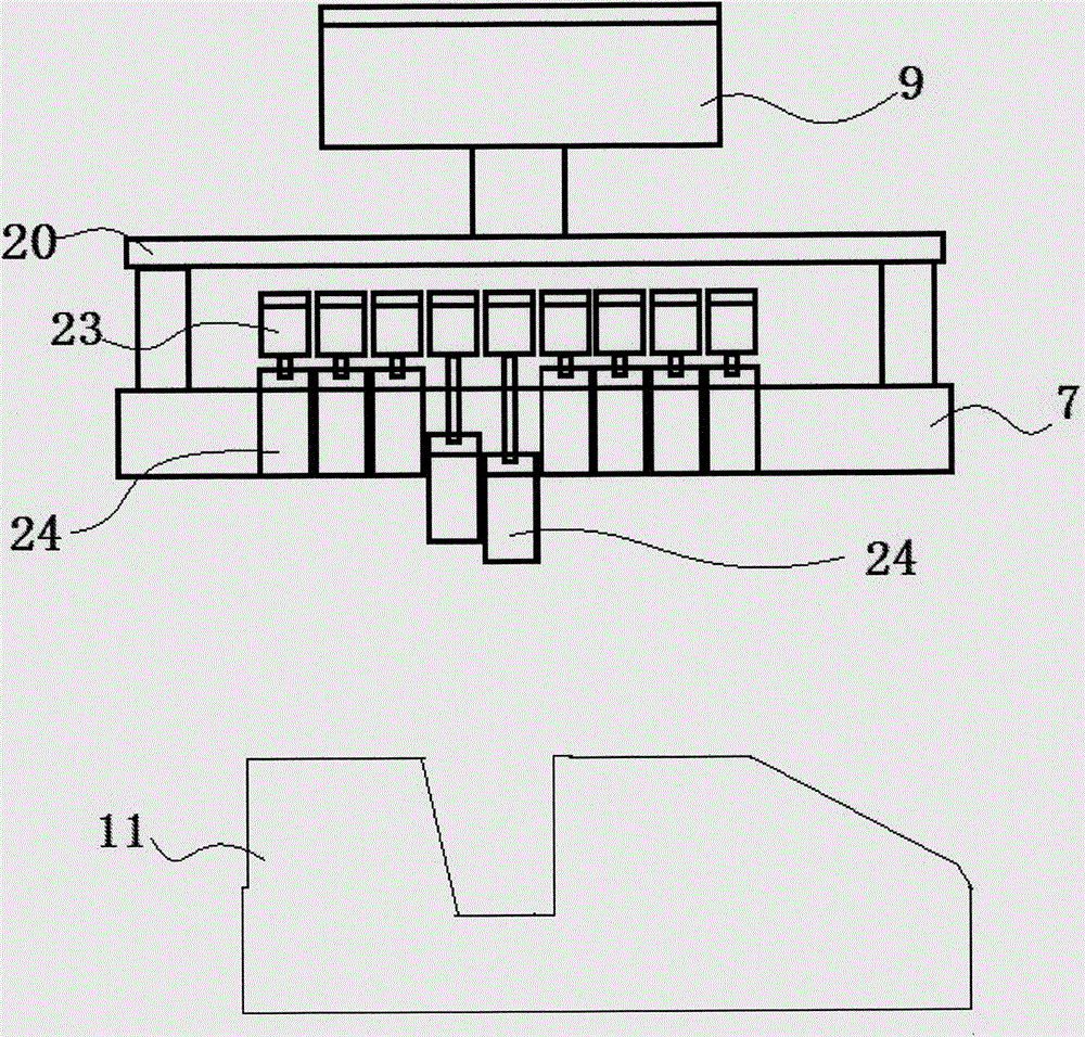
[0031] Such as figure 1 , 2 , 3, 4, and 5, the specific embodiment of the present invention is a molding machine without sand filling dead angle, including a frame 1, a sliding rod 2, a lower sand box 3, a middle box 4, and an upper sand box 5. , Lower pressure plate 6, Upper pressure plate 7, Compaction cylinder 8, Upper pressure cylinder 9, Sand shooting cylinder 10, Mould 11, Control module. There are four sets of parallel slide bars 2 vertically arranged on one side of the frame 1. An upper sand box 5 and a lower sand box 3 are arranged from top to bottom. An upper box movement cylinder 14 is provided between the upper sand box 5 and the slide rod 2, and a lower box movement cylinder is provided between the lower sand box 3 and the slide rod 2. 12. A lower pressing plate 6 is also arranged under the lower sand box 3, the lower pressing plate 6 is c...


PUM


Abstract

The invention discloses a molding machine without sand filling dead angles. Sand blasting barrels are arranged on the outer sides of sliding bars in the vertical direction respectively, shutters are arranged at inlets of the sand blasting barrels, and the sand blasting barrels are connected with an air pump; sand blasting ports used for blasting sand are formed in the lower portions of the sand blasting barrels and provided with sand blasting valves, and the sand blasting ports of the two sand blasting barrels are connected with the side surface of an upper sand box and the side surface of a lower sand box respectively. One sides of the sliding bars are horizontally provided with a middle box pushing rod, a middle box pushing rod guide rail and a middle box mold pushing cylinder, wherein the middle box pushing rod is arranged at the front end of the middle box mold pushing cylinder, and the middle box pushing rod guide rail is arranged on the lower portion of the middle box pushing rod. According to the molding machine without the sand filling dead angles and an application method thereof, blasting through the multiple blasting ports are conducted in the mode that the blasting ports are vertical or the lateral surfaces intersect by an angle, the dead angles can be effectively decreased, and the yield can be improved significantly; adjustable and stretchable protrusions are arranged on an upper pressing plate and can be timely adjusted according to the deep concave rate of a mold, and it is ensured that overmuch sand is accumulated on local parts in the sand blasting process.

Description

Technical field [0001] The invention relates to the field of molding machines, in particular to a molding machine without sand-filling dead corners and a method of use thereof. Background technique [0002] When using the moulding machine for soil-stained sand casting, first use air pressure to blow the molding sand into the sand box equipped with the mold, and then use hydraulic pressure, air pressure or electric motor to squeeze the molding sand, and then take out the mold and then take it out The sand bodies behind the mold are combined to form a complete sand body, and then moved to a casting platform or position for casting. [0003] In the sand shooting process, the existing molding machine combines the upper sand box and the lower sand box to rotate upwards or downwards. Usually, the sand is shot in one direction by the weight of the sand particles. If there is a mold in the middle, the other Dissatisfaction with sand will appear on the side or in the middle. [0004] Existi...

Claims


Application Information

Patent Timeline
Patent Type & Authority Applications(China)
IPC IPC(8): B22C15/24
Inventor 王刚
Owner ZONSAN MACHINERY CO LTD
Learn More